CARBURETOR

(1) Piston valve spring
(2)Starter plunger assembly
(3) Upper bracket
(4) O-ring
(5) Lower bracket
(6) Throttle stop screw
(7) Synchronizing screw
(8) Washer
(9) Main jet
(10) Valve seat assembly
(11) Float
(12)Gasket
(13) Drain screw
(14) Float chamber
(15) Pilot jet
(16) Needle jet
(17) Piston valve
(18) Diaphragm
(19) Jet needle assembly
|
SPECIFICATIONS |
|
|
Main jet |
# 107 |
|
Main air jet |
# 70 |
|
Jet needle |
Y-20 |
|
Needle jet |
Ø 3.22 |
|
Pilot jet |
# 36.5 |
|
Pilot air jet |
# 210 |
|
Fuel level |
1.0 ± 1.0 mm (0.039 ±0.039 in) |
|
Float height |
16.0± 1.0 mm (0.630 ± 0.039 in) |
|
Pilot screw |
Preset |
|
Float valve seat |
Ø2.0 |
|
Engine idle speed |
1,050 ±50 rpm |
Special tools:
|
A |
VACUUM GAUGE: |
|
P/No. YU-08030 |
|
|
B |
FUEL LEVEL GAUGE: |
|
P/No. YM-01312 |
SECTION VIEW
MAIN METERING SYSTEM
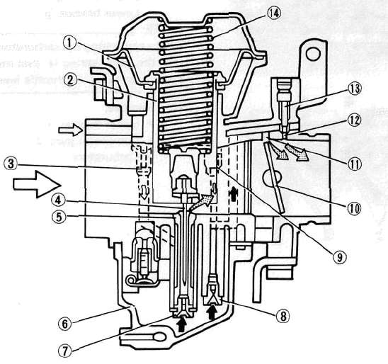
(1) Diaphragm
(2) Piston valve
(3) Main air jet
(4) Jet needle
(5) Needle jet
(6) Float chamber
(6) Main jet
(7) Pilot jet
(9) Pilot air jet
(10) Throttle valve
(11) By-pass hole .
(12) Pilot outlet
(13) Pilot screw
(14) Spring
|
A |
|
AIR |
|
B |
|
MIXTURE |
|
C |
|
FUEL |
CARBURETOR OVERHAUL
REMOVAL
1. Remove Carburetor assembly (Refer to engine removal section.)
NOTE:
The following parts can be cleaned and inspected without disassembly.
• Piston valve
• Jet needle
2. Disconnect the drain hoses, fuel hoses and throttle cable
3. Number each carburetor before removing it from carburetor brackets.
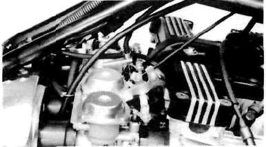
4. Loosen starter lever screws
5. Remove starter lever shaft (1), starter lever (2) and Lower bracket (3)
NOTE:
When separating the carburetors be sure not to lose the small spring (4) that may fall out. This spring connects the throttle levers.
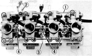
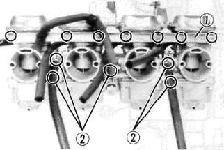
6. Remove the upper bracket (1), carburetor joint (2) and carburetors
DISASSEMBLY
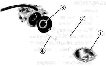
1. Remove the vacuum chamber cover (1), spring (2), vacuum piston (3) and jet needle (4)
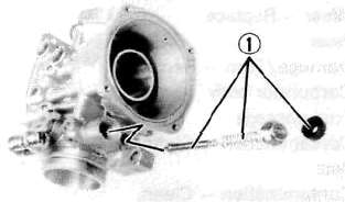
2. Remove the starter plungers (1)
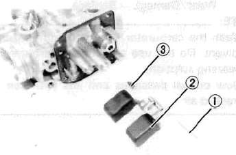
3. Remove float chamber cover, Float pin (1), float(2) and Needle valve (3)
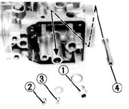
4. Remove the Valve seat (1), Pilot jet (2), Main jet (3) and Needle jet (4)
NOTE:
Remove the needle jet toward the vacuum piston.
INSPECTION
1. Inspect:
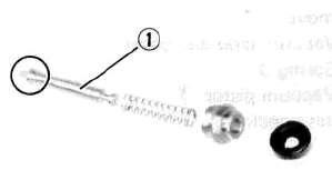
• Starter plunger (1) for wear
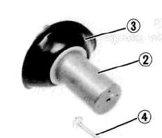
• Vacuum piston (2) for wear
• Throttle valve diaphragm (3) for tears
• Jet needle (4) for bends and/or wear
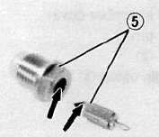
• Needle valve and valve seat (5) for wear.
• Float for cracks or other damage.
• Carburetor body
• Fuel passage for contamination — Clean with carburetor cleaner
• Jets for contamination — Clean with carburetor cleaner.
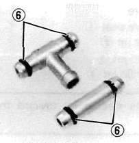
• O-rings (Carburetor joint) (6) for wear, nicks, compression or other damage
Replace all damaged and worn components. .
NOTE:
• Wash the carburetor in a petroleum-based solvent. Do not use any caustic carburetor cleaning solutions.
• Blow out all passages and jets with compressed air.
FLOAT HEIGHT ADJUSTMENT
This is a preliminary step to approximate the correct float setting following reassembly It does not replace the need to set the fuel height as described bylow.
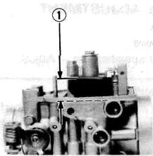
Float height measurement steps:
• Hold the carburetor in an upside down position.
• Incline the carburetor at 60 — 70° (so that the end of the float valve does not hang down as a result of float weight)
• Measure the distance from the mating surface of the float chamber (gasket removed) to the top of the float.
NOTE:
The float should be just resting on, but not depressing, the spring loaded inlet needle.
Float Height:
16.0+1.0 mm (0.630±0.039 in)
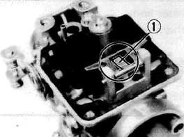
Float height adjustment step:
• Remove the float.
• Adjust float height by bending the float tang (1) slightly.
• Repeat the procedure for other carburetors.
FUEL LEVEL ADJUSTMENT
This is the final step in setting the floats, performed after the carburetors have been reassembled and offering greater precision than described above.
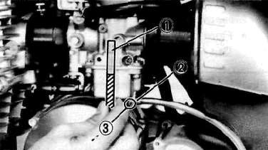
Measurement steps (carburetors installed on motorcycle):
• Place the motorcycle on a level surface.
• Use a garage jack under the engine to ensure that the carburetor is positioned vertically.
• Connect the Fuel Level Gauge (1) (YM-01312) to the drain nozzle (2).
• Loosen the drain screw (3) and start the engine.
• Check the fuel level, one carburetor at a time.
Measurement steps (carburetors not installed)
• Use a jig, vise, "Workmate" style bench or similar device to hold the carburetor bank vertically
• Place a level across the tops of the carbs to ensure the bank is level side to side.
• Use a remote fuel supply with inline shut-off valve positioned just above the carb bank to supply fuel.
• Connect the Fuel Level Gauge (1) (YM-01312) to the drain nozzle (2).
• Loosen the drain screw (3).
• Check the fuel level, one carburetor at a time.
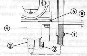
Fuel Level: (a), below the carburetor body
1.0 ± 1.0 mm (0.039 ± 0.039 in)
(4) Float chamber (5) Carburetor body
Adjustment steps:
• Remove the carburetors if necessary. Drain. Remove the float bowl.
• Adjust float level by bending the float tang (1) slightly.
• Repeat the procedure for the other carburetors.
AIR CLEANER AND CRANKCASE VENTILATIONS SYSTEM
Refer to "CHAPTER 2" for air cleaner maintenance.
(1) Air cleaner (2) Carburetor
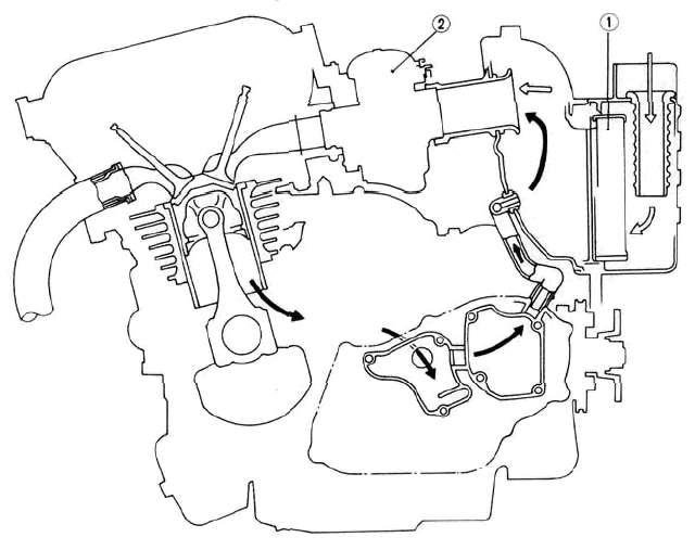
|
A |
|
FRESH AIR |
|
B |
|
BLOW BY GAS |
- Printer-friendly version
- Log in to post comments


