Circuit diagram
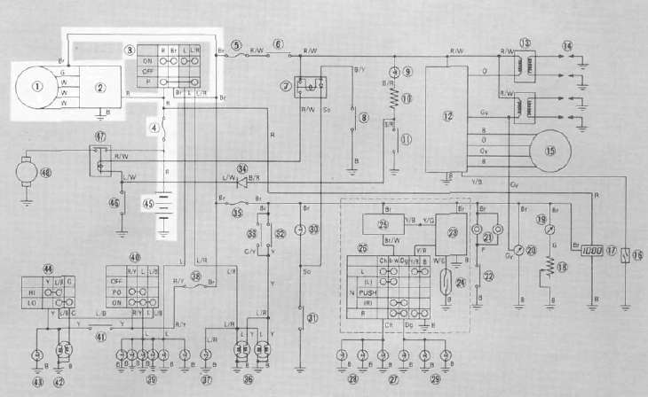
A. C. Generator
1. Checking method
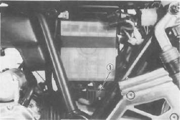
a. Connect D. C. voltmeter to the battery terminals.
b. Start the engine.
c. Accelerate engine to approximately 2,000 r/min or more and check generated voltage,
Generated voltage:
14.5 ± 0.3 V at 20°C (68°F)
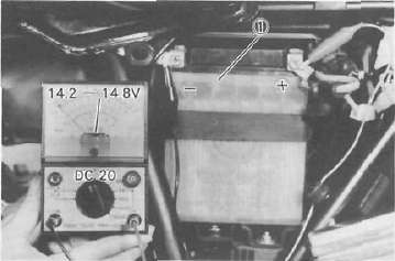
1 Battery
d. If the indicated voltage cannot be reached, then perform the tests in step 2.
CAUTION: Never disconnect leads from the battery while the generator is in operation. If the battery is disconnected, the voltage across the generator terminals will increase, damaging the semiconductors.
2. Resistance test of field coil and stator coil
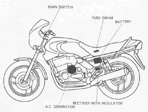
a. Remove the seat. Disconnect the 2-pin connector and 3-pin connector from the A. C. Generator.
b. Check the resistance between terminals. If resistance is out of specification, coil is broken. Check the coil connections. If the coil connections are good, then the coil is broken inside and it should be replaced.
Field coil resistance (Green-Brown): 4.0 Ω ± 10 % at 20°C (68°F)
Stator coil resistance (White-White): 0.46 Ω ± 10 % at 20°C (68°F)
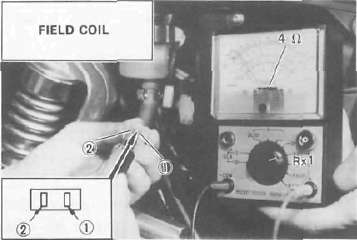
1 Brown 2. Green
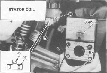
1. White 2. White
Voltage regulator
The AC Voltage Regulator is a small and, normally, very reliable component. Due to its construction, it is lightweight and free from the wear and misadjustment associated with mechanical voltage regulators. If the following inspection reveals that the regulator is faulty, it cannot be adjusted and must be replaced.
1. Rectifier with regulator
1. Checking AC Voltage regulator
a. Remove the seat.
b. Remove the left side cover.
c. Measure the specific gravity of the battery fluid. If it is less than 1.260, remove the battery and recharge until it is more than 1.260.
d. Check the battery terminals and couplers for looseness.
e. Connect two Yamaha pocket testers to the regulator coupler as illustrated.
CAUTION: Be careful not to let the tester leads short circuit when connecting them to the regulator snap connector leads.
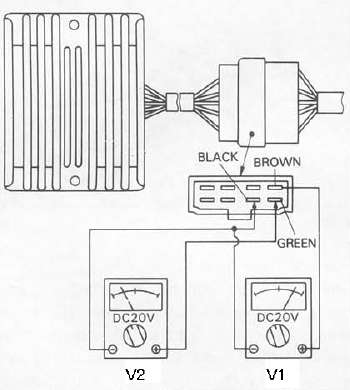
f. Turn the main switch on. Make sure that V2 is less than 1.8V.
NOTE: Do not turn on lights or signals.
g. Make sure that V2 gradually increases up to 9 - 11V when the engine is started and its revolutions go up.
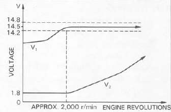
h. Make sure that V, maintains the level of 14.2 — 14.8 V even when engine revolutions increase.
i. If these levels are not maintained, the regulator is defective and must be replaced.
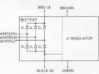
2. Checking the silicon rectifier
a. Check the silicon rectifier as specified using the Yamaha pocket tester.
|
Checking element |
Pocket tester connecting point |
Good |
Shorted |
Open |
|
| (+) (red) | (-)
(black) |
||||
|
D, |
d | a | O | O | X |
| a | d | x | 0 | X | |
|
D2 |
d | b | O | o | X |
| b | d | X | o | X | |
|
D3 |
d | c | O | o | X |
| c | d | X | o | X | |
|
D4 |
a | e | O | o | X |
| e | a | X | 0 | X | |
|
D5 |
b | e | O | o | X |
| e | b | X | o | X | |
|
D6 |
c | e | O | o | X |
| e | c | X | o | X | |
O: Continuity
x: Discontinuity (∞)
b. Even if only one of the elements is broken, replace the entire assembly.
CAUTION: The silicon rectifier can be damaged if subjected to overcharging. Special care should be taken to avoid a short circuit and/or incorrect connection of the positive and negative leads at the battery. Never connect the rectifier directly to the battery to make a continuity check.
- Printer-friendly version
- Log in to post comments