VALVE CLEARANCE ADJUSTMENT

1 Valve lifter 2 Pad 3 Retainer 4 Spring seat
Valve Clearance (Cold):
Intake: 0.11 -0.20 mm (0.004- 0.008 in)
Exhaust: 0.21- 0.30 mm (0.008- 0.012 in)
Measurement

1. Remove:
• Seat
• Fuel tank
• Horns
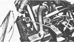
• Ignition coil mount bolts (1)
2. Disconnect the spark plug caps

3. Remove:
• Ignition coils
• Spark plugs
• Cylinder head cover
• Left crankcase cover
4. Measure the valve clearance
NOTE:.
Be sure piston is at Top Dead Center (TDC) on compression stroke when measuring clearance.
Valve clearance measurement steps:
•Turn the crankshaft counterclockwise with a 19 mm (0.75 in) spanner.
NOTE:
Valve clearance must be measured when the engine is cool to the touch.

(1) Pickup coil mark
(2) TDC for No. 1 cylinder
(3) Firing range for the No. 1 cylinder
• Align the "T" mark (2) on the timing plate with the pickup coil mark (1) . When the "T" mark is aligned with the stationary pointer (2) . the piston is at top dead center (TDC).

• Measure the valve clearance using a Feeler Gauge (3).
• Record the measured amount if the clearance is incorrect.
Intake Valve (cold): 0.11- 0.20 mm (0.004- 0.008in)
Exhaust Valve (cold): 0.21- 0.30 mm (0.008- 0.012 in)
Measure valve clearance, in sequence, for Nos. 2, 4, and No. 3 cylinders.
Out of specification - Adjust clearance.
Firing Sequence: 1 -2-4-3

[A] Crankshaft counterclockwise turning angle. [Bl Cylinder [C] Combustion

Adjustment
1. Remove carburetors Refer to CHAPTER 3 "ENGINE REMOVAL".

2. Loosen the cam chain tensioner end plug (1)
3. Remove the cam chain tensioner (2)

4. Remove:
•Cam chain guide (Upper) (1)
•Cam cap I3 (2)
•Cam cap E3 (3)
• Dowel pins
5. Remove:
•Cam chain sprocket bolts
•Cam caps
•Dowel pins

•Cam shafts (1)
•Cam chain sprockets (2)
NOTE:
Fasten safety wire to the cam chain to prevent it from falling into the crankcase.

6. Remove:
• Valve lifter (1)
• Pad (2)

Note the installed pad number (3). Round off the value as required:
|
Pad range |
Pad Availability: 25 increments |
|
|
No. 120 ~ No. 240 |
1.20 mm (0.047 in) 2.40 mm (0.094 in) |
Pads stepped in 0.05 mm (0.002 in) increments |
|
Note: Thickness of each pad is marked on the pad side wall. |
||
|
• Round off the hundredths digit of the installed pad number to the nearest 0.05 mm increment. |
||
|
Hundredths digit |
Rounded valve |
|
|
0 or 2 |
0 |
|
|
5 |
(NOT ROUNDED OFF) |
|
|
8 |
10 |
|
7. Select the proper pad from the appropriate chart (next 2 pages, links below)
EXAMPLE:
Installed pad number = 175 (1.75 mm)
Rounded off digit = 175
NOTE:
Pads can only be selected in 0.05 mm (0.02 in) increments.
* Locate the "Rounded off Pad Number" on the chart, and then find the measured valve clearance. The point where these coordinates intersect is the new pad number.
NOTE:
Use the new pad number as a guide only as the number must be verified.

8. Install:
• Pad (1)
• Valve lifter (2)
• Cam shaft
• Cam chain sprocket
Refer to CHAPTER 3 "ENGINE ASSEMBLY"

9. Recheck the valve clearance.
If the clearance is incorrect, repeat all of the clearance adjustment steps until the proper clearance is obtained.
Assembly
1. Reverse removal steps.
Inspect the head cover gasket and replace it if damaged.
2. Tighten:
• Cylinder head cover bolts
• Fuel tank bolts
Head Cover Bolt: 10 Nm (1.0 m.kg, 7.2 ft-lb)
Fuel Tank Bolt: 10 Nm (1.0 m.kg, 7.2 ft-lb)
- Printer-friendly version
- Log in to post comments
