Chapter 7, Appendices
Chapter 7, AppendicesSpecifications
SpecificationsSPECIFICATIONS
General Specifications
|
XJ750RH |
|
|
Basic color |
New Yamaha Black or Brilliant Red |
|
Dimensions: |
|
|
Overall length |
2,110 mm (83.1 in) |
|
Overall width |
860 mm (33.9 in) |
|
Overall height |
1,120 mm (44.1 in) |
|
Seat height |
775 mm (30.5 in) |
|
Wheel base |
1,445 mm (56.9 in) |
|
Minimum ground clearance |
140 mm (5.5 in) |
|
Caster (steering head angle) |
28° |
|
Trail |
114 mm (4.49 in) |
|
Weight: |
|
|
Net |
218 kg (480 lb) |
|
Engine: |
|
|
Type |
D.O.H.C. air-cooled, gasoline |
|
Bore x stroke x cylinders |
65.0 x 56.4 mm x 4 (2.559 x 2.220 in x 4) |
|
Displacement |
748 cc (45.64 cu.in) |
|
Compression ratio |
9.2 : 1 |
|
Lubrication: |
|
|
Lubrication system |
Pressure lubricated, wet sump |
|
Delivery pump type |
Trochoid |
|
Carburetion: |
|
|
Manufacture |
HITACHI |
|
Type |
HSC32, constant velocity |
|
Rated venturi size |
25.3 mm (0.996 in) |
|
Air filter: |
Dry type element |
|
Ignition: |
|
|
Type |
Battery ignition (Full transistor ignition) |
|
Spark plug |
BP7ES (NGK) or W22EP (ND) |
|
Charging: |
|
|
Type |
Three-phase, regulated alternator |
|
Manufacture, I.D. No. |
HITACHI, LD119-08 |
|
Maximum output |
14V 19A |
|
Battery type |
YB14L-A2 |
|
Battery dimensions |
89 x 116 x 134 mm (3.50 x 6.54 x 5.28 in) |
|
Regulator/Rectifier |
S8534, I.C. type, full wave |
|
Regulating voltage (No. load) |
14.2-14.8V |
|
Starting: |
Electric starter |
|
Primary drive: |
|
|
Type |
Spur gear |
|
Teeth, ratio |
97/58 1.672 |
|
Clutch: |
Wet, multiple disc |
|
Transmission: |
|
|
Type |
Constant mesh, 5-speed drum shifter |
|
Teeth, ratio 1st |
35/16 2.187 |
|
2nd |
30/20 1.500 |
|
3rd |
30/26 1.153 |
|
4th |
28/30 0.933 |
|
5th |
26/32 0.812 |
|
XJ750RH |
|
|
Secondary type: |
|
|
Type |
Shaft drive |
|
Transmission output: |
|
|
Type, teeth, ratio |
Spur gear, 49/36,1.361 |
|
Middle gear case: |
|
|
Type, teeth, ratio |
Bevel gear, 19/18, 1.055 |
|
Final gear case: |
|
|
Type, teeth, ratio |
Bevel gear, 32/11, 2.909 |
|
Chassis: |
|
|
Frame |
Tubular steel double cradle |
|
Suspension: Front (type, travel) |
Telescopic fork (Pneumo-mechanical) |
|
|
150 mm (5.91 in) |
|
Rear (type, travel) |
Swing arm, 80 mm (3.15 in) |
|
Tires: Front |
3.25H19-4PR,Tubeless |
|
Rear |
120/90-18 65H,Tubeless |
|
Brakes: Front |
Dual hydraulic disc |
|
Rear |
Drum brake |
|
Fuel tank: Total |
19 lit (5.0 US. gal) |
|
Reserve |
4.1 lit (1.08US.gal) |
|
Wheels: Front |
MT1.85 x 19, Cast Aluminum |
|
Rear |
MT2.15 x 18, Cast Aluminum |
Maintenance Specifications
1. Engine
Engine oil capacity:
Total amount 3,500 cc (3.70 US.qt)
Oil and filter change 2,800 cc (2.96 US.qt)
Oil change 2,500 cc (2.64 US.qt)
Recommended lubricant:
If temperature does not go below 5°C (40°F) SAE 20W/40 SE motor oil
If temperature does not go above 15°C (60°F) SAE 10W/30 SE motor oil
Cranking pressure (at seal level): 11 kg/cm2 (156 psi)
Maximum difference between cylinders: 1 kg/cm2 (14 psi)
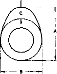
Camshafts:
|
Dimensions |
Standard size |
Wear limit |
|
|
Intake |
A |
36.80 mm (1.449 in) |
36.65 mm (1.443 in) |
|
B |
28.00 mm (1.102 in) |
27.85 mm (1.096 in) |
|
|
C |
8.80 mm (0.346 in) |
- |
|
|
Exhaust |
A |
35.80 mm (1.449 in) |
35.65 mm (1.404 in) |
|
B |
28.00 mm (1.102 in) |
27.85 mm (1.096 in) |
|
|
C |
7.80 mm (0.307 in) |
- |
|
Camshaft bearing, surface diameter: 24.967 ~ 24.980 mm (0.9830 ~ 0.9835 in)
Camshaft-to-cap clearance:
Standard 0.020 ~ 0.054 mm (0.0008 ~ 0.0021 in)
Maximum 0.160 mm (0.006 in)
Camshaft runout limit 0.1 mm (0.004 in)
Valve spring:
Allowable tilt from vertical


|
|
Inner Intake/Exhaust |
Outer Intake/Exhaust |
|
Free length |
35.9 mm (1.413 in) |
39.5 mm (1.555 in) |
|
Spring rate |
2.36 kg/mm (132.2 lb/in) |
4.58 kg/mm (256.5 Ib/in) |
|
Installed length (valve closed) |
31.0 mm (t.220 in) |
34.0 mm (1.339 in) |
|
Installed pressure (valve closed) |
9.0 kg (19.81b) |
19.1 kg (42.1 lb) |
|
Compressed length (valve open) |
IN: 22.5 mm (0.886 in) EX: 23.5 mm (0.925 in) |
IN: 25.5 mm (1.004 in) EX: 26.5 mm (1.043 in) |
|
Wire diameter |
2.8 mm (0.110 in) |
3.9 mm (0.154 in) |
|
Number of windings |
7.75 |
6.0 |
|
Winding O.D. |
20.6 (+0.3 -0) mm |
29.4 (+0 -0.3) mm |
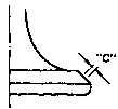
Valves:
Valve stem run-out maximum 0.03 mm (0.0012 in)
Valve seat width standard/maximum: 1.0 mm (0.0039 in)/2.0 mm (0.080 in)


INTAKE
|
Clearance (Cold engine) |
0.11 ~0.15mm |
|
"A" head diameter |
33 ±0.1 mm |
|
"B" face width |
2.3 mm |
|
"C" seat width |
1.0 ±0.1 mm |
|
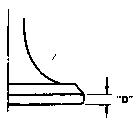
"D" margin thickness (minimum) |
1.2 ±0.2 mm |
|
Stem diameter (O.D.) |
7-0.010 -0.025 mm (0.2756 -0.0004 _0.0010 in) |
|
Guide diameter (I.D.) |
7+0.012 -0 mm (0.2756 +0.0005 -0 in) |
|
Stem-to-guide clearance |
0.010 ~ 0.037 mm |
EXHAUST
|
Clearance (Cold engine) |
0.16~0.20mm (0.006 ~0.008 in) |
|
"A" head diameter |
28 ±0.1 mm (1.2205 ±0.0039 in) |
|
"B" face width |
2.3 mm (0.0906 in) |
|
"C" seat width |
1.0 ±0.1 mm (0.0394 ± 0.0039 in) |
|
"D" margin thickness (minimum) |
1.0 ± 2.0 mm (0.0392 ± 0.0079 in) |
| Stem diameter (O.D.) |
7 -0.025 -0.040 mm (0.2756 -0.0010 _0.0016 in) |
| Guide diameter (I.D.) |
7+0.012 -0 mm (0.2756 +0.0005 -0 in) |
| Stem-to-guide clearance | 0.025 ~ 0.062mm (0.0010 ~ 0.0020 in) |
|
Cylinder and piston: |
|
|
Cylinder material |
Aluminum alloy |
|
Cylinder liner |
Pressed in; special cast iron |
|
Bore size: Standard |
65.00 mm (2.5591 in) |
|
Wear limit |
65.10 mm (2.5630 in) |
|
Cylinder taper limit |
0.05 mm (0.0020 in) |
|
Cylinder out-of-round limit |
0.01 mm (0.0004 in) |
|
Piston clearance: Standard |
0.030 ~ 0.050 mm |
|
Maximum |
0.1 mm (0.0039 in) |
|
Piston ring: |
Top |
2nd |
Oil |
|
|
Design |
|
|
|
|
|
End gap (installed): |
Standard |
0.15 ~ 0.35 mm (0.0059 ~ 0.0318 in) |
0.15 ~ 0.35 mm (0.0059 ~ 0.0138 in) |
0.3 ~ 0.9 mm (0.0018 ~ 0.035 in) |
|
|
Limit |
1.0 mm (0.0394 in) |
1.0 mm (0.0394 in) |
1.5 mm (0.0591 in) |
|
Side clearance: |
Standard |
0.03 ~ 0.07 in (0.0012 ~ 0.0028 in) |
0.02 ~ 0.06 in (0.008 ~ 0.0024 in) |
- |
|
|
Limit |
0.15 mm (0.0059 in) |
0.15 mm (0.0059 in) |
- |
 Barrel
 Taper
Taper Expander
|
Crankshaft: |
||
|
Crank journal/bearing oil clearance |
0.004 ~ 0.064 mm (0.0016 ~ 0.0025 in) |
|
|
Main journal run-out (maximum) |
0.040 mm (0.0016 in) |
|
|
Connecting rods: |
||
|
Rod bearing oil clearance |
0.03 ~ 0.09 mm (0.0012 ~ 0.0035 in) |
|
|
Oil pump: |
||
|
Housing-to-outer rotor clearance |
0.09 - 0.15 mm (0.0035 ~ 0.0059 in) |
|
|
Outer rotor-to-inner rotor clearance |
0.03 ~ 0.09 mm (0.0012 - 0.0035 in) |
|
|
Clutch: |
||
|
Friction plate: |
Thickness/q'ty |
3.0mm(0.12in)/8 |
|
|
Minimum thickness |
2.8 mm (0.11 in) |
|
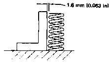
Clutch plate: |
Thickness |
1.6 mm (0.063 in)/7 |
|
|
Warp limit |
0.05 mm (0.0020 in) |
|
Clutch spring: |
Length/q'ty |
41.2 mm (1.622 in)/5 |
|
|
Minimum length |
40.2 mm (1.583 in) |
|
|
Spring rate |
1.22 kg/mm (68.3 lb/in) |
|
Clutch lever free play (at lever pivot point) |
2~ 3 mm (0.08 ~ 0.12 in) |
|
|
Transmission shaft run-out maximum: |
0.08 mm (0.0031 in) |
|
|
Middle gear case lash: |
0.1 ~ 0.2 mm (0.0039 - 0.0079 in) |
|
LUBRICATION CHART

OIL PRESSURE INFORMATION
Relief Valve Opening 5.0 kg/cm2 (71 psi)
Bypath Valve Opening 1.0 kg/cm2 (14 psi)
2. Carburetion
|
Manufacturer |
HITACHI |
|
Model I.D. No. |
5G200 |
|
Main jet |
#120 |
|
Pilot jet |
#40 |
|
Starter jet |
#40 (00.9) |
|
Jet needle |
Y-13 |
|
Fuel level |
3±1 mm (0.118±0.039 in) |
|
Pilot screw |
Preset |
|
Air jet. Main |
#80 |
|
Air jet. Pilot |
#225 |
|
Float valve seat |
02.0 |
|
Engine idle speed |
1,050 r/min |
3. Chassis
|
Wheels and tires: |
2.0 mm (0.079 in) |
|
|
Tire pressure (cold) |
Front |
Rear |
|
Up to 90 kg (198(b) load* |
1.8 kg/cm2 (26 psi) |
2.0 kg/cm2 (28 psi) |
|
90 kg (198 lb) ~ 215 kg (474 lb) load* |
2.0 kg/cm2 (28 psi) |
2.3 kg/cm2 (32 psi) |
|
High speed riding |
2.3 kg/cm2 (32 psi) |
2.5 kg/cm2 (36 psi) |
|
Minimum tire tread depth |
0.8 mm (0.03 in) |
0.8 mm (0.03 in) |
|
Brakes: |
||
|
Recommended fluid |
DOT #3 |
|
|
Pad wear limit |
4.0 mm (0.16 in) |
|
|
Rear brake lining wear limit |
2 mm (0.08 in) |
|
|
Brake disc maximum deflection |
0.15 mm (0.006 in) |
|
|
Brake disc minimum thickness |
4.5 mm (0.18 in) |
|
|
Front brake free play |
1.0 ~ 2.0 mm (0.04 ~ 0.08 in) |
|
|
Rear brake free play |
20 ~ 30 mm (0.8 ~1.2 in) |
|
*Total weight of accessories, etc. excepting motorcycle.
|
Front forks: |
|
|
Travel |
150 mm (5.91 in) |
|
Spring free length |
604.9 mm (23.81 in) |
|
Spring preload length |
582.9 mm (22.95 in) |
|
Spring rate: |
|
|
0~132mm(0~5.20in) |
0.4 kg/mm (22.4 lb/in) |
|
132 ~ 150 mm (5.20 ~ 5.91 in) |
0.5 kg/mm (28.0 lb/in) |
|
Fork oil capacity (each side) |
309 cc (10.5 oz) |
|
Oil type |
Yamaha Fork Oil 20Wt or equivalent |
|
Standard air pressure |
0.4 kg/cm2 (5.7 psi) |
|
Rear shock absorbers: |
|
|
Spring free length |
227.8 mm (8.97 in) |
|
Spring preload length |
207.8 mm (8.18 in) |
|
Spring rate: |
|
|
0~55mm (0~ 2.17 in) |
1.7 kg/mm (95.2 lb/in) |
|
55 ~ 80 mm (2.17~3.15 in) |
2.1 kg/mm (117.6 lb/in) |
|
Travel |
80 mm (3.15 in) |
4. Electrical
Ignition timing retarded: 7° at 1,050 r/min
Ignition timing advance:

|
Spark plug: |
NGK BP7ES or ND W22EP |
|
Electrode gap |
0.7 ~ 0.8 mm |
|
Spark plug cap resistance |
5.0 kΩ (No. 1, No. 4), |
|
Pick up coil: |
|
|
Resistance |
65012 ± 20% at 20°C (68° F) |
|
Ignition coil type: Spark gap |
HITACHI CM 12-09 |
|
Primary resistance |
2.5Ω ± 10%at20°C(68°F) |
|
Secondary resistance |
11 kΩ±20%at20°C(68°F) |
|
Starter motor type: |
ND, ADB4D2 |
|
Armature coil resistance |
0.014Ω ± 6% at 20°C (68°F) |
|
Brush length: Standard |
12.0 mm (0.472 in) |
|
Minimum |
8.5 mm (0.33 in) |
|
Brush spring pressure |
800 ± 150g (28.24 ± 5.30 oz) |
|
Armature mica undercut |
0.6 mm (0.024 in) |
|
Battery type: |
YUASAYB14L-A2 |
|
Charging rate |
1.4 Amps for 10 Hours |
|
Generator type: |
HITACHI LD119-08 |
|
Output |
14V-19A at 5,000 r/min |
|
Field (inner) coil resistance |
4.0Ω±10%at20°C(68°F) |
|
Stator (outer) coil resistance |
0.46Ω ± 10% at 20° C (68° F) |
|
Regulator type: |
I.C. (S8534) |
|
Regulated voltage |
14.5 ± 0.3V |
|
Allowable amperage |
3A |
|
Starter relay switch: |
|
|
Cut-in voltage |
Less than 8V |
|
Headlight |
12V, 60W/55W |
|
Tail/brake light |
12V, 8W (3CP)/27W (32CP) |
|
Flasher light |
12V,27W(32CP)x4 |
|
License light |
12V, 8W(3CP)x2 |
|
Pilot lights: |
|
|
Turn |
12V, 3.4Wx2 |
|
High beam |
12V,3.4Wx 1 |
|
Neutral |
12V, 3.4Wx1 |
|
Warning |
12V,3.4Wx1 |
|
Meter light |
12V. 3.4Wx2 |
|
Auxiliary low beam light |
12V,35Wx1 |
Torque Values
Torque ValuesTightening torque
|
Part to be tightened |
Part name |
Thread size |
Q'ty |
Tightening torque |
Remarks |
|
|
m-kg |
ft-lb |
|||||
|
ENGINE: |
||||||
|
Cylinder head |
Nut |
M10 P1.25 |
12 |
3.2 |
23.1 |
Apply oil. |
|
Cylinder head cover |
Bolt |
M6 P1.0 |
20 |
1.0 |
7.2 |
|
|
Spark plug |
- |
|
4 |
2.0 |
14.5 |
|
|
Cylinder |
Nut |
M8 P1.25 |
2 |
2.0 |
14.5 |
Cam chain case |
|
Cam shaft cap |
Bolt |
M6 P1.0 |
20 |
1.0 |
7.2 |
Tighten in 3 stages. |
|
Cam sprocket |
Bolt |
M7 P1.0 |
4 |
2.0 |
14.5 |
|
|
Cam chain tensioner |
Nut |
M8 P1.25 |
1 |
0.9 |
6.5 |
|
|
Cam chain tensioner |
Bolt |
M8 P1.25 |
1 |
1.5 |
10.8 |
|
|
Connecting rod |
Nut |
M7 P0.75 |
8 |
2.5 |
18.1 |
|
|
Generator (rotor) |
Bolt |
M10 P1.25 |
1 |
5.5 |
39.8 |
|
|
Drain plug |
Bolt |
M14 P1.5 |
1 |
4.3 |
31.0 |
Crankcase drain |
|
Oil filter |
Bolt |
M20 P1.5 |
1 |
1.5 |
11.0 |
|
|
Pump cover |
Screw |
M6 P1.0 |
|
0.7 |
5.1 |
|
|
Strainer cover |
Bolt |
M6 P1.0 |
13 |
0.7 |
5.1 |
|
|
Crankcase |
Flange |
M8 P1.25 |
12 |
2.4 |
17.5 |
|
|
Clutch boss |
Nut |
M20 P1.0 |
1 |
7.0 |
50.6 |
|
|
Clutch spring screw |
Bolt |
M6 P1.0 |
5 |
1.0 |
7.2 |
|
|
Change pedal |
Bolt |
M6 P1.0 |
1 |
0.8 |
5.8 |
|
|
Neutral switch |
- |
M10 P1.25 |
1 |
2.0 |
14.5 |
|
|
Exhaust pipe |
Nut |
M6 P1.0 |
8 |
0.75 |
5.4 |
|
|
Part to be tightened |
Part name |
Thread size |
Q'ty |
Tightening |
Remarks |
|
|
m-kg |
ft-lb |
|||||
|
SHAFT DRIVE: |
||||||
|
Middle gear: |
||||||
|
Drive shaft |
Nut |
M34 P1.5 |
1 |
11 |
80.0 |
Stake. |
|
Mount cover |
Screw |
M8 P1.25 |
4 |
2.5 |
18.1 |
Stake. |
|
Driven shaft |
Nut |
M14 P1.5 |
1 |
12 |
87.0 |
Use LOCTITE |
|
Bearing cap |
Flange bolt |
M8 P1.25 |
4 |
2.5 |
18.1 |
|
|
Final gear: |
||||||
|
Drive shaft |
Nut |
M14 P1.5 |
1 |
11 |
80.0 |
|
|
Bearing housing |
Flange bolt |
M10 P1.25 |
2 |
2.3 |
16.6 |
|
|
Bearing housing |
Nut |
M8 P1.25 |
6 |
2.3 |
16.6 |
|
|
Oil mount screw |
Plug |
M14 P1.5 |
1 |
2.3 |
16.6 |
|
|
Oil drain screw |
Plug |
M14 P1.5 |
1 |
2.3 |
16.6 |
|
|
Bearing retainer |
- |
M65 P1.5 |
1 |
11 |
80.0 |
Left hand screw |
|
CHASSIS: |
||||||
|
Engine mounting bolt: |
||||||
|
Front, upper |
Nut |
M10 P1.25 |
1 |
4.2 |
30.4 |
|
|
Front, under |
Nut |
M10 P1.25 |
2 |
4.2 |
30.4 |
|
|
Rear |
Nut |
M10 P1.25 |
2 |
7.0 |
50.6 |
|
|
Engine mounting stay: |
||||||
|
Front |
Nut |
M8 P1.25 |
4 |
2.0 |
14.5 |
|
|
Handle crown & Steering shaft |
Bolt |
M14 P1.25 |
1 |
5.4 |
39.1 |
|
|
Handle crown & Inner tube |
Nut |
M8 P1.25 |
1 |
2.0 |
14.5 |
|
|
Handle crown & Handle holder |
Bolt |
M8 P1.25 |
2 |
2.0 |
14.5 |
|
|
Front fork: |
||||||
|
Under bracket & Inner tube |
Bolt |
M8 P1.25 |
4 |
2.0 |
14.5 |
|
|
Front wheel shaft |
Nut castle |
M14 P1.5 |
1 |
10.7 |
77.4 |
|
|
Front wheel axle pinch bolt |
Nut salf locking |
M8 P1.25 |
2 |
2.0 |
14.5 |
|
|
Pivot shaft |
Bolt |
M22 P1.5 |
1 |
0.55 |
4.0 |
Taper roller |
|
Rear wheel shaft |
Nut castle |
M14 P1.5 |
1 |
10.7 |
77.4 |
|
|
Rear shock absorber (Upper) |
Nut cap |
M10 P1.25 |
2 |
3.0 |
21.7 |
|
|
Rear shock absorber (Lower) |
L Nut cap R Bolt |
M10 P1.25 |
2 |
3.0 |
21.7 |
|
|
Footrest |
Bolt |
M10 P1.25 |
2 |
4.2 |
30.4 |
|
|
Tension bar & Brake plate |
Bolt |
M8 P1.25 |
1 |
2.0 |
14.5 |
|
|
Tension bar & Rear arm |
Bolt |
M8 P1.25 |
1 |
2.0 |
14.5 |
|
|
Camshaft lever & Camshaft |
Bolt |
M6 P1.0 |
1 |
0.9 |
6.5 |
|
|
Disc brake section: |
||||||
|
Brake disc & Hub (Front) |
Bolt |
M8 P1.25 |
12 |
2.0 |
14.5 |
Lock washer |
|
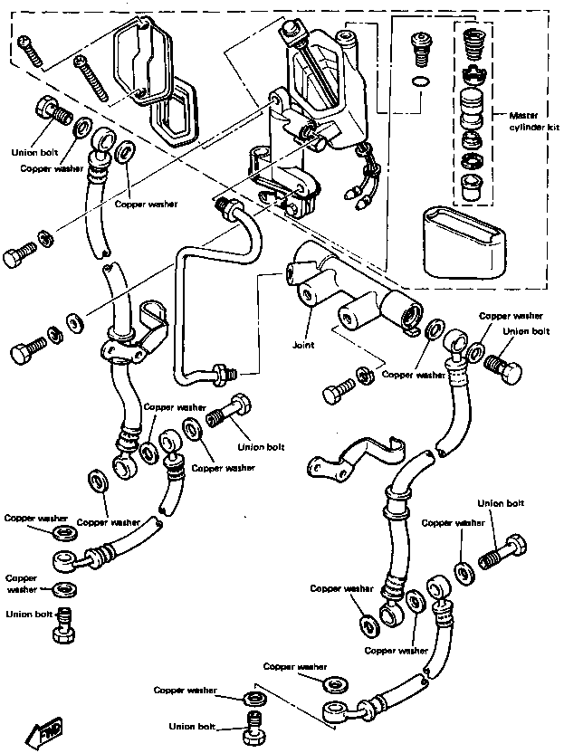
Master cylinder & |
Bolt union |
M10 P1.25 |
1 |
2.0 |
14.5 |
|
|
Brake hose & Joint |
Bolt union |
M10 P1.25 |
1 |
2.6 |
18.8 |
|
|
Caliper & Brake hose |
Bolt union |
M10 P1.25 |
1 |
2.6 |
18.8 |
|
|
Caliper & Front fork (Front) |
|
M10 P1.25 |
1 |
4.5 |
32.5 |
|
|
Caliper bleed screw (Front) |
|
M8 PI.25 |
1 |
0.6 |
4.3 |
|
|
Front fender |
Bolt |
M8 PI.25 |
4 |
1.0 |
7.2 |
|
|
Part to be tightened |
Part name |
Thread size |
Q'ty |
Tightening torque |
Remarks |
|
|
m-kg |
ft-lb |
|||||
|
Pivot shaft |
Bolt |
M22 P1.5 |
1 |
10.0 |
72.3 |
Lock washer |
|
Final gear & Rear arm |
Nut |
M10 P1.25 |
4 |
4.2 |
30.4 |
|
|
Cross joint |
Hexagon bolt |
M8 P1.25 |
4 |
4.4 |
31.8 |
|
|
Muffler bracket & Frame |
Bolt |
M10 P1.25 |
3 |
4.3 |
31.1 |
|
|
Rear fender |
Bolt |
M10 P1.25 |
2 |
3.2 |
23.1 |
|
|
Muffler bracket & Muffler |
Bolt |
M10 P1.25 |
2 |
2.5 |
18.1 |
|
|
DEFINITION OF TERMS: |
|
|
m-kg |
= Meter-kilogram(s) (usually torque) |
|
9 |
= Gram(s) |
|
kg |
= Kilogram(s) (1,000 grams) |
|
lit |
= Liter(s) |
|
km/lit |
= Kilometer(s) per liter (fuel consumption) |
|
cc |
= Cubic centimeter(s) (cm3) (volume or capacity) |
|
kg/mm |
= Kilogram(s) per milimeter (usually spring compression rate) |
|
kg/cm2 |
= Kilogram(s) per square centimeter (pressure) |
Consumer Information
Consumer InformationCONSUMER INFORMATION
Notice The information presented represents results obtainable by skilled drivers under controlled road and vehicle conditions, and the information may not be correct under other conditions.
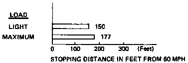
STOPPING DISTANCE
This figure indicates braking performance that can be met or exceeded by the vehicles to which it applies, without locking the wheels, under different conditions of loading and with partial failures of the braking system.
FULL OPERATIONAL SERVICE BRAKE
("Partial failure" information is not applicable and is not included)
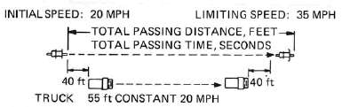
ACCELERATION AND PASSING ABILITY
This figure indicates passing times and distances that can be met or exceeded by the vehicles to which it applies, in the situations diagrammed below. The low-speed pass assumes an initial speed of 20 mph. and a limiting speed of 35 mph. This high-speed pass assumes an initial speed of 50 mph. and a limiting speed of 80 mph.
LOW-SPEED PASS
HIGH-SPEED PASS
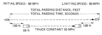
SUMMARY
Low-speed pass ........................................ 353.0 feet: 7.15 seconds
High-speed pass ........................................ 883.4 feet: 8.4 seconds
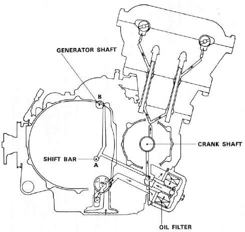
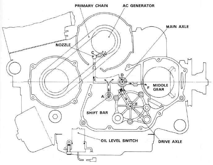
Lubrication Diagrams
Lubrication DiagramsLUBRICATION DIAGRAMS


Cable Routing
Cable RoutingCABLE ROUTING


Parts Illustrations
Parts IllustrationsPARTS ILLUSTRATIONS
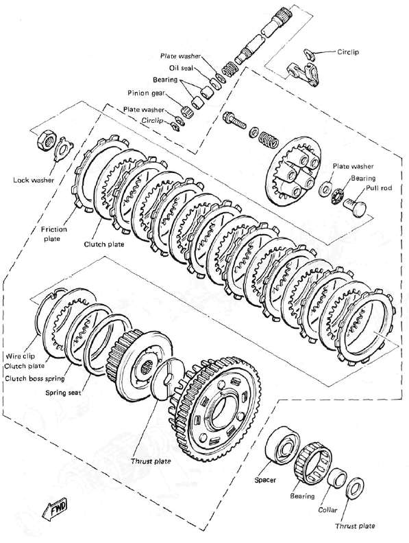
Clutch
ClutchCLUTCH
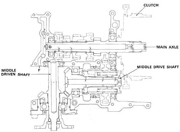
Transmission
Transmission
TRANSMISSION

Middle Gear Damper
Middle Gear DamperMIDDLE GEAR/DAMPER

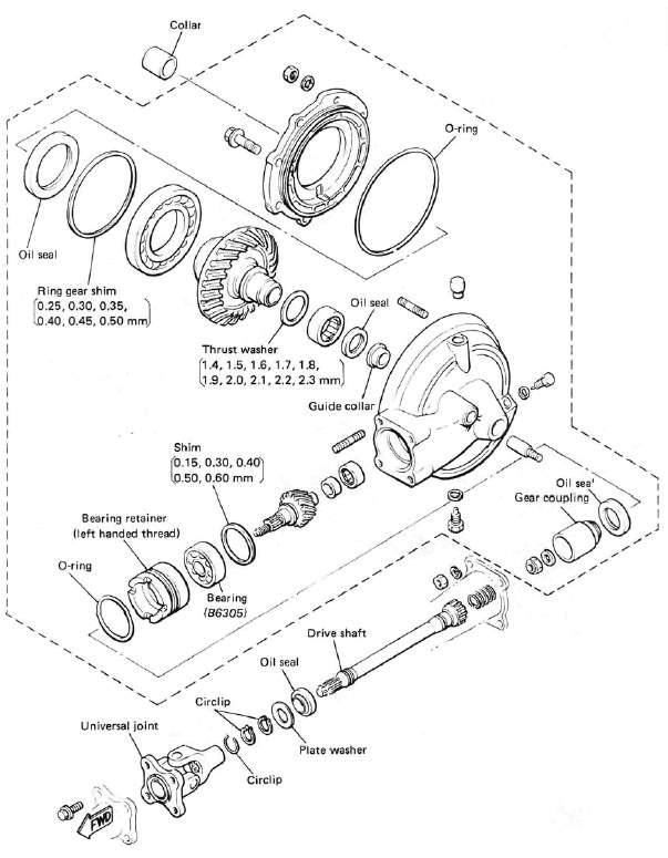
Final Gear / Driveshaft
Final Gear / DriveshaftFINAL GEAR / DRIVE SHAFT
Front Wheel
Front WheelFRONT WHEEL

Front Brake
Front BrakeFRONT BRAKE (MASTER CYLINDER)
Front Fork
Front ForkFRONT FORK

Rear Wheel
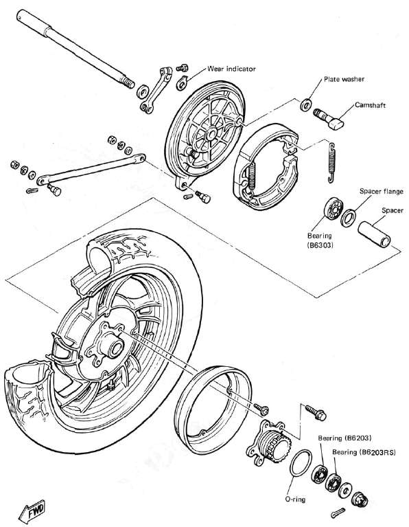
Rear WheelREAR WHEEL
Meter
MeterMETER

Middle Gear Damper
Middle Gear DamperMIDDLE GEAR/DAMPER
Electrical Component Locations
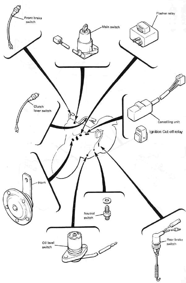
Electrical Component LocationsELECTRICAL COMPONENTS

Wiring Diagram
Wiring DiagramWIRING DIAGRAM
COLOR CODE
R.......Red
B.......Black
G.......Green
W.......White
P.......Pink
0.......Orange
V.......Yellow
L.......Blue
Sb.......Sky blue
Ch.......Chocolate
Gy......Gray
Dg.......Dark green
Br.......Brown
L/B......Blue/Black
W/V......White/Yellow
R/W......Red/White
Rr*Y......Red/Yellow
W/G......White/Green
8/R......Black/Red
B/W......Black/White
Br/W.....Brown/White
WR......Yellow/Red
B/Y......Black/Yellow
L/Y......Bhue/Yellow
t-/W......Blue/White
Y/G......Yellow/Green
