Transmission, Clutch and Middle gear
Transmission, Clutch and Middle gearTRANSMISSION

3. Crankcase assembly a. Apply Yamaha bond #4 sealant or equivalent to the crankcase mating surface. Be very careful not to allow any sealant to come in contact with the oil gallery "O-ring" and crankshaft bearings. It is extremely important, however, that sealant be applied around the case stud holes. Apply sealant to within 2 — 3 mm (0.08 — 0.12 in) of the bearings.
CAUTION: Failure to apply sealant here will result in reduced oil pressure and possible crank seizure.
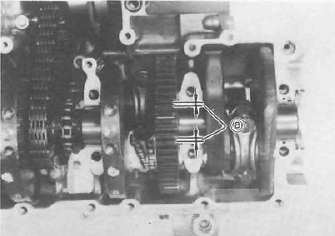
a. 2 — 3 mm (0.08 — 0.12 in) Do not apply sealant
b. The crankcases are assembled by placing the upper case half on the bench and lowering the lower case onto it.
NOTE: Be sure that shift fork No. 2 engages the groove in the 2nd pinion gear on the main axle.
CAUTION: Before installing and torquing the crankcase bolts, check to make sure the transmission is functioning properly by shifting it by hand with the shift cam.

c. Start installation of the crankcase bolts with the center crankshaft area bolts. Place the two bolts without washers in the oil filter area.
d. The crankcase bolts should be torqued in proper sequence. Refer to the tightening sequence in the illustration.

1. Engine ground wire
CRANKCASE TIGHTENING SEQUENCE LOWER CASE

UPPER CASE
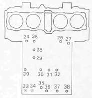
8 mm bolt: 24 Nm (2.4 m kg. 1 7 ft lb) 6 mm bolt: 12 Nm (1.2 m kg. 8 7 ft-lb)
4. Oil pump and strainer cover
a. Place the oil pump drive chain on the transmission main axle.
b. Install the thrust plate onto the transmission main axle.
c. Install the oil pump drive sprocket onto the main axle without the spacer collar and place the oil pump drive chain on its sprocket.

1. Oil pump drive sprocket
d. Place the drive chain on the oil pump driven sprocket and install the pump on the crankase. The "O-ring" should be installe properly.

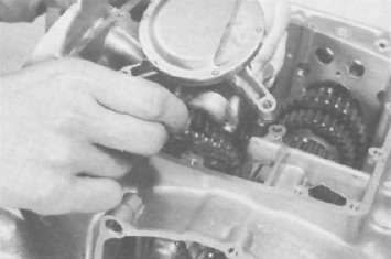
e. Install the drive chain cover on the oil pump and secure with the 2 shouldered bolts and one normal 6 mm bolt.
Tlightening torque:
12 Nm (1.2 mkg, 8.7 ft-lb)
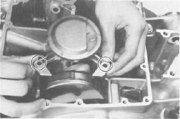
f. Install the strainer cover and torque the bolts to the specification.
Tightening torque:
7 Nm (0.7 m-kg, 5.1 ft lb)
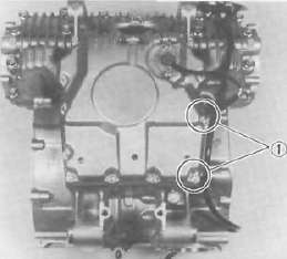
1 Wire clamps
CLUTCH

5. Clutch assembly
a. Insert the spacer coller into the oil pump drive sprocket.
b. Install the primary driven gear (clutch housing) without the bearing and inner spacer.
CAUTION: Be sure that the oil pump drive gear tabs engage the clutch housing grooves on it's back or the tabs will be damaged when tightening the clutch boss securing nut.

1. Spacer collar
c. Install the primary driven gear bearing and inner spacer into the clutch housing.

1 Driven gear bearing 2. Inner spacer
d. Install the large thrust plate and clutch boss onto the main axle.
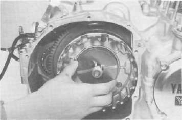
e. Install a new lock washer-and nut and tighten the nut to the specified torque. Use the clutch boss holder (special tool).
Tightening torque:
70 Nm (7.0 nrvkg, 50 ft-lb)

1. Clutch boss holder
f. Bend the lock washer tabs along the nut flats.
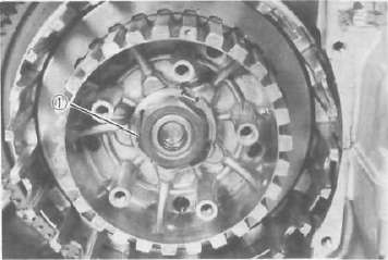
1. Lock tab
g. Install the clutch plates and friction plates alternately on the clutch boss, starting with a friction plate and ending with a friction plate.
h. Install the plate washer, thrust bearing, and clutch pull rod into the clutch pressure plate from inside.

1. Pull rod 2. Thrust bearing 3. Plate washer
i. Install the pressure plate assembly onto the clutch boss.
NOTE: Pressure plate has a dot on it which must line up with the dot on clutch boss.

j. Install the clutch springs and screws. Tighten the screws.
Clutch screw torque: 8 Nm (0.8 m-kg, 5.8 ft lb)
k. Install the oil collector plate.

1. Oil collector plate
I. Set the gear of the clutch pull rod on the pressure plate facing approximately 45° from horizontal toward the rear; set the clutch lever (if installed) on the right crankcase cover parallel to the gasket surface and install the cover to the crankcase. Do not forget to install two dowel pins.

m. If the clutch lever has been removed, install the lever return spring and lever on the shaft after installing the right crankcase cover. In this case make sure that the punch mark on the lever should align with the mark on the crankcase cover when pushing the lever towards the front by hand and then install the circlip.

1 Push
6. Middle gear (installation only, refer to page for the middle gear adjustment). a. Install the middle drive gear assembly with the proper size of shim(s) and secure it with the bearing retainers and new "TORX" screws.
Tightening torque: 25 Nm (2.5 mkg, 18 ft-lb)
b. Stake the screw heads to the dents on the bearing retainers with a center punch.

c. Install the driven gear assembly with the proper size of shims and secure it with the bolts. Apply a thread locking compound such as "LOCTITE" to the bolt threads.
Tightening torque:
25 Nm (2.5 mkg, 18 ft-lb)

1 Shims
d. Install the middle gear case half moon seal onto the crankcase.

1. Seal