XJ550H/J/K Service Manual
XJ550H/J/K Service ManualTable of contents
Chapter 1 General Information
Chapter 1 General InformationMOTORCYCLE IDENTIFICATION
A. Frame serial number
The frame serial number is stamped into the right side of the steering head pipe.
B. Engine serial number
The engine serial number is stamped into the elevated part of the right section of the engine.
NOTE:
The first three digits of these numbers are for model identifications; the remaining digits are the unit production number.
C. Vehicle identification number
The vehicle identification number is stamped on the label attached on the right side of the steering head pipe.
NOTE:
The vehicle identification number is used to identify your motorcycle and may be used to register your motorcycle with the licensing authority in your state.
Starting serial number:
XJ550RH.............4U8-000101

SPECIAL TOOLS
The proper special tools are necessary for complete and accurate tune-up and assembly. Using the correct special tool will help to prevent damage from improper tools or in-provised techniques.
A. For tune-up
1. Compression gauge
2. Timing light
3. Tachometer
4. Tappet adjusting tool P/N. 90890-01245-00

This tool is necessary to replace valve adjusting pads. This can also be used for the XS750, XS850. XS1100 and XJ65Q.
5. Vacuum gauge
P/N. TLU-11080-30-02

This gauge is needed for carburetor synchronization.
B. For engine service
1. Clutch hub holder
P/N. TLM-90910-42-00

This tool is used to hold the clutch when removing or install ing the clutch boss lock nut.
2. Valve guide reamer
P/N. P/N. 90890-04066-00

This tool must be used when replacing the valve guide.
3. Valve seat cutter
P/N. TLM-90910-43-20

This tool is needed to re-surface the valve seat.
4. Valve guide remover P/N. 90890-04064-00

This tool must be used to remove the valve guides.
5. Valve guide installer
P/N. 90890-04065-00

This tool is needed for proper installation of the valve guides.
6. Valve spring compressor
P/N. 90890-01253-00

This tool must be used for removing and installing the valve
assemblies,
7. Piston ring compressor P/N. 90890-04047-00

This tool is used to compress piston rings when installing the cylinder.
8. Piston base
P/N. 90890-01067-00

Use 4 of these to hold the pistons during cylinder installation.
9. Rotor puller
P/N. 90890-01080-00

This tool is needed to remove the A,C. Generator rotor.
10. Rotor puller attachment P/N. 90890-04052-00

This tool is needed when removing the A.C. Generator rotor together with the rotor puller.
11. Rotor holding tool P/N. 90890-04067-00

This tool is used to hold the A.C. Generator rotor during removal and installation.
12. Dial gauge stand
P/N. 90890-01258-00

13. Dial gauge
P/N. 90890-03097-00

This dial gauge is used to determine piston position for correct timing.
14. YlCSshutoff tool
P/N. TLM-11080-25-00

This tool is needed for carburetor synchronization,
15. Fuel level gauge
P/N. 90890-01312-00
This tool is needed to measure the carburetor fuel level.
This tool is needed to hold the dial gauge.
16. Fuel level gauge adapter P/N. 90890-01329-00

This tool is needed when measuring the carburetor fuel level together with fuel level gauge.
C. For electrical components The uses of thee tools are described in CHAPTER 6. 1. Pocket tester
P/N. 90890-03104-00

2. Electro tester
P/N. 90890-03021-00

Chapter 2. Periodic Inspections and Adjustments
Chapter 2. Periodic Inspections and AdjustmentsIntroduction and Intervals
Introduction and IntervalsINTRODUCTION
This chapter includes all information necessary to perform recommended inspection and adjustments. These preventative maintenance procedures, if followed, will insure more reliable vehicle operation and a longer service life. The need for costly overhaul work will be greatly reduced. This information applies not only to vehicles already in service, but also to new vehicles that are being prepared for sale. Any service technician performing preparation work should be familiar with this entire chapter.
MAINTENANCE INTERVALS CHARTS
Proper periodic maintenance is important. Especially important are the maintenance services related to emissions control. These controls not only function to ensure cleaner air but are also vital to proper engine operation and maximum performance. In the following tables of periodic maintenance, the services related to emissions control are grouped separately.
PERIODIC MAINTENANCE EMISSION CONTROL SYSTEM
|
No. |
Item |
Remarks |
Initial break-in |
Thereafter every |
||
|
1,000 km (600 mil or 1 month |
5.000 km (3,000 mi) or 7 months |
4,000 km (2,500 mi) or 6 months |
8,000 km (5,000 mi) or 12 months |
|||
|
1* |
Cam chain |
Adjust chain tension. |
o |
0 |
O |
|
|
2* |
Valve clearance |
Check and adjust valve clearance when engine is cold. |
o |
O |
||
|
3 |
Spark plugs |
Check condition. Adjust gap/Clean. Replace after initial 13,000 km (8,000 mi) or 18 months and thereafter every 12,000 km (7,500 mi) or 18 months. |
o |
O |
Replace every 12,000 km (7,500 mi) or 18 months |
|
|
4* |
Crankcase ventilation system |
Check ventilation hose for cracks or damage. Replace if necessary. |
o |
o |
||
|
5* |
Fuel line |
Check fuel hose and vacuum pipe for cracks or damage. Replace if necessary. |
o |
O |
||
|
6" |
Exhaust system |
Check for leakage. Retighten as necessary. Replace gasket(s) if necessary. |
o |
O |
||
|
7' |
Carburetor synchronization |
Adjust synchronization of carburetors. |
o |
O |
||
|
8' |
Idle speed |
Check and adjust engine idle speed. Adjust cable free play if necessary. |
o |
o |
||
It is recommended that these items be serviced by a Yamaha dealer or other qualified mechanic.
GENERAL MAINTENANCE/LUBRICATION
|
No. |
Item |
Remarks |
Type |
Initial break-in |
Thereafter every |
|||
|
1,000 km (600 mi) or 1 month |
5,000 km (3,000 mi) or 7 months |
4,000 km (2,500 mi) or 6 months |
8,000 km (5,000 km) or 12 months |
16.000 km (10,000 mi) or 24 months |
||||
|
1 |
Engine oil |
Warm-up engine before draining. |
Refer to page 2-9. |
O |
O |
O |
||
|
2 |
Oil filter |
Replace. |
- |
o |
O |
O |
||
|
3 |
Air filter |
Clean with compressed air. |
- |
O |
O |
|||
|
4* |
Brake system |
Adj uSt free play Front: Replace pads if necessary. Rear: Replace shoes if necessary. |
- |
O |
o |
0 |
||
|
5" |
Clutch |
Adjust free play |
- |
o |
o |
o |
||
|
6 |
Drive chain |
Check chain condition. Adjust and lubricate chain thoroughly. |
Yamaha chain and cable lube or SAE 10W/30 motor oil |
CHECK CHAIN TENSION AND LUBE EVERY 500 km (300 mi). |
||||
|
7* |
Control and meter cable |
Apply chain lube thoroughly. |
Yamaha chain and cable lube or SAE 10W/30 motor oil |
O |
o |
o |
||
|
8 |
A.C. generator |
Replace generator brushes. Replace at initial 13.000 km (8,000 mil and thereafter every 16.000 km 110,000 mi) |
Replace |
|||||
|
9 |
Brake/clutch lever pivot shaft |
Apply chain lube lightly. |
Yamaha chain and cable lube or 10W/ 30 motor oil |
o |
o |
|||
|
10 |
Change/Brake pedal shaft pivot |
Apply chain lube lightly. |
Yamaha chain and cable lube or 10W/ 30 motor oil |
o |
o |
|||
|
11 |
Center and side stand pivots |
Apply chain lube lightly. |
Yamaha chain and cable lube or 10W/ 30 motor oil |
0 |
o |
|||
|
12 |
Front fork oil |
Drain completely. Refill to specification. |
Yamaha fork oil 10 wt or equivalent |
O |
||||
|
13 |
Steering Ball Bearing and races |
Check bearings assembly for looseness. Moderately repack every 16,000 km (10,000 mi). |
Medium weight wheel bearing grease |
o |
o |
Repack |
||
|
14 |
Wheel bearings |
Check bearings for smooth rotation, Replace if necessary. |
_ |
o |
o |
|||
|
15 |
Battery |
Check specific gravity. Check breather pipe for proper operation. |
- |
o |
0 |
|||
It is recommended that these items be serviced by a Yamaha dealer or other qualified mechanic.
Chassis
ChassisBrakes
Brakes1. Brake adjustment
a. Front brake lever free play adjustment
The brake can be adjusted by simply adjusting the free play of the brake lever. The piston in the caliper moves forward as the brake pad wears out, automatically adjusting the clearance betweenthe brake pads and brake disc.
CAUTION:
Proper lever free play is essential to avoid excessive brake drag.

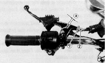
1. Adjuster 2. Lock nut a. 5 — 8 mm (0,2 ~ 0.3 in)
1) Loosen the adjuster lock nut on the brake lever.
2) Turn the adjuster so that the brake lever movement at the lever end is 5 ~ 8 mm {0.2 ~ 0.3 in) before the adjuster contacts the master cylinder piston.
3) After adjusting, tighten the lock nut.
b. Rear brake pedal height adjustment
1) Loosen the adjuster lock nut (for pedal height).
2) By turning the adjuster bolt clockwise or counterclockwise, adjust the brake pedal position so that its top end is approximately 20 mm (0.78 in) below the foot rest top end.
3) Secure the adjuster lock nut.
WARNING:
After adjusting the pedal height, the brake pedal free play should be adjusted.

1. Adjuster bolt 3. Footrest
(for pedal height) 4. Pedal height 20 mm (0.8 in)
2. Lock nut 5. Free play 20 — 30 mm (0.8—1.2 in)
c. Rear brake pedal free play adjustment
Turn the adjuster on the brake rod clockwise or counterclockwise to provide the brake pedal end with a free play of 20— 30 mm (0.8- 1.2 in).
NOTE:
Check to see whether or not the brake light operates correctly after adjusting.
2. Front brake pad and rear brake shoe check
a. Front brake pad
To check, look at the pad wear indicator in back of the caliper. If any pad is worn to the wear limit, replace both the pads in the caliper. Front

1. Wear indicator
b. Rear brake shoe
To check, see the wear indicator position while depressing the brake pedal. If the indicator reaches to the wear limit line, replace the shoes.
1. Wear limit 2, Wear indicator
3. Brake fluid
Insufficient brake fluid may allow air to enter the brake system, possibly causing the brake to become ineffective. Check the brake fluid level and replenish when necessary observing these precautions:

1. Lower level
a. Use only the designated quality brake fluid; otherwise, the rubber seals may deteriorate, causing leakage and poor brake performance.
Recommended brake fluid: DOT#3
b. Refill with the same type and brand of brake fluid; mixing fluids may result in a harmful chemical reaction and lead to poor performance.
c. Be careful that water or other contamination does not enter the master cylinder when refilling. Water will significantly lower the boiling point and may result in vapor lock.
d. Brake fluid may erode painted surfaces or plastic parts. Always clean up spilled fluid immediately.
Drive Chain and Wheels
Drive Chain and WheelsDrive chain
1. Drive chain tension check
NOTE:
Before checking and/or adjusting, rotate the rear wheel through several revolutions and check the tension several times to find the tightest point. Check and/or adjust chain tension with rear wheel in this "tight chain" position.
Inspect the drive chain with the center stand put up. Check the tension at the position shown in the illustration. The normal vertical deflection is approximately 35- 40 mm (1.4 ~ 1.6 in). If the deflection exceeds 35 ~ 40 mm (1.4~1.6 in) adjust the chain tension.

a. 35*^40 mm (1.4**-1.6 in
2. Drive chain tension adjustment
1. Loosen the rear brake adjuster.
2. Remove the cotter pin of the rear wheel axle nut with pliers.
3. Loosen the rear wheel axle nut.
4. Loosen the adjust bolt lock nuts on each side. To tighten the chain turn chain puller adjust bolts clockwise. To loosen the chain turn adjust bolts counterclockwise and push wheel forward. Turn each bolt exactly the same amount to maintain correct axle alignment (There are marks on each side of rear arm and on each chain puller; use them to check for proper alignment).

1. Lock nut 2. Adjuster 3. Marks for align 4. Rear wheel axle nut 5. Cotter pin
5. After adjusting, be sure to tighten the lock nuts and the rear wheel axle nut.
6. Insert the cotter pin into the rear wheel axle nut and bend the end of the cotter pin as shown in the illustration (if the nut notch and the cotter pin hole do not match tighten the nut slightly to match).

CAUTION:
Always use a new cotter pin on the rear axle nut.
NOTE:
Excessive chain tension will overload the engine and other vital parts; keep the tension within the specified limits.
7. In the final step, adjust the play in the brake pedal.
3. Drive chain lubrication The chain consists of many parts which work against each other. If the chain is not maintained properly, it will wear out rapidly. Without lubrication the chain could wear out within 500 km (300 mi), therefore, form the habit of periodically servicing the chain. This service is especially necessary when riding in dusty conditions.
1. Use YAMAHA CHAIN/CABLE LUBE or any of the many brands of spray type chain lubricant. First, remove dirt and mud from the chain with a brush or cloth and the spray the lubricant between both rows of side plates andon all center rollers. This should be performed every 500 km (300 mi).
2. To clean the entire chain, first remove the chain from the motorcycle, dip it in solvent and clean out as much dirt as possible. Then take the chain out of the solvent and dry it. After drying lubricate the chain to prevent the formation of rust.
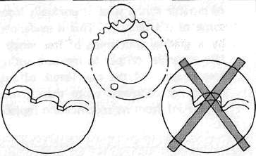
Tubeless tires and aluminum wheels
This motorcycle is equipped with aluminum wheels designed to be compatible with either tube or tubeless tires. Tubeless tires are installed as standard equipment.
WARNING:
Do not attempt to use tubeless tires on a wheel designed for use only with tube-type tires. Tire failure and personal injury may results from sudden deflation.
Tube-type Wheel — Tube-type tires only
Tubeless-type Wheel — Tube-type or Tubeless tires When using tube-type tires, be sure to install the proper tube also.
Tubeless tire

Tube-type tire

To insure maximum performance, long service, and safe operation, note the following precautions:
1. Check tire pressure, before riding, adjust as necessary.
2. Before operation, always check the tire surfaces for wear and/or damage; look for cracks, glass, nails, metal fragments, stones, etc. Correct any such hazard before riding.
3. Always inspect the aluminum wheels before a ride. Place the motorcycle on the center stand and check for cracks, bends or warpage of the wheels. Do not attempt even small repairs to the wheel. If a wheel is deformed or cracked, it must be replaced.
4. Tires and wheels should be balanced whenever either one is changed or replaced. Failure to have a wheel assembly balanced can result in poor performance, adverse handling characteristics, and shortened tire life.
5. After installing a tire, ride conservatively to allow the tire to seat itself on the rim properly. Failure to allow proper seating may cause tire failure resulting in damage to the motorcycle and injury to the rider.
6. After repairing or replacing a tire, check to be sure the valve stem lock nut is securely fastened. If not, torque it as specified.
Tightening torque: 0.15 m-kg (1.1 ft-lb)
Fuel Petcock
Fuel Petcock
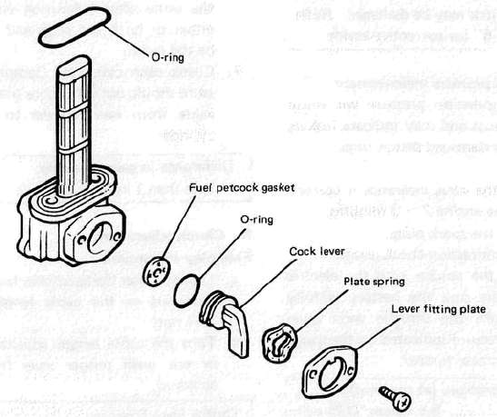
If the fuel petcock is
leaking or excessively contaminated, it should be removed from the fuel
tank and inspected.
1.
Remove the fuel tank and position it so that fuel will not spill when
the petcock is removed.
2.
Remove the petcock and inspect the filter screen. Replace the filter if
seriously contaminated.
3.
Remove the screws on the front and rear of the petcock and remove
the plate, gasket, lever, and diaphragm.
4.
Inspect all components and
replace any that are damaged. If the diaphragm is in any way damaged,
or the petcock body gasket surfaces scratched or corroded, the petcock
assembly must be replaced. If there is abrasive damage to any
component, the fuel tank must be drained and flushed.
5.
Reassemble the petcock and install it on the fuel tank.
Lubrication Points
Lubrication PointsCable inspection and lubrication
WARNING:
Damage to the outer housing of the various cables, may cause corrosion and often free movement will be obstructed. An unsafe condition may result so replace such cables as soon as possible.
1. If the inner cables do not operate smoothly, lubricate or replace them.
Recommended lubricant:
Yamaha Chain and Cable Lube or
SAE 10W/30 motor oil
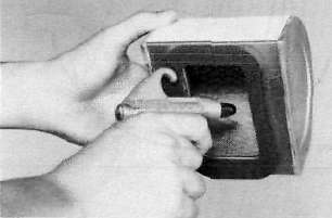
I. Throttle cable and grip lubrication
The throttle twist grip assembly should be greased when the cable is lubricated, since the grip must be removed to get at the end of the throttle cable. Two screws clamp the throttle housing to the handlebar. Once these two are removed, the end of the cable can be held high to pour in several drops of lubricant. With the throttle grip disassembled, coat the metal surface of the grip assembly with a suitable all-purpose grease to cut down friction.
Brake and change pedal/brake and clutch levers
Lubricate the pivoting parts of each lever and pedal.
Recommended lubricant:
Yamaha Chain and Cable Lube or SAE 10W/30 motor oil
Center and side stand pivots
Lubricate the center and side stands at their pivot points.
Recommended lubricants:
Yamaha Chain and Cable Lube or SAE 10W/30 motor oil
Suspension and Steering
Suspension and SteeringFront fork oil change
WARNING:
Securely support the motorcycle so there is no danger of it falling over.
1. Raise the motorcycle or remove the front wheel so that there is no weight on the front end of the motorcycle. Remove the handlebar if necessary.
2. Remove the rubber cap from the top of each fork.
3. The spring seat and fork spring are retained by a stopper ring (spring wire circlip). it is necessary to depress the spring seat and fork spring to remove the stopper ring. Remove the stopper ring by carefully prying out one end with a small screwdriver,

4. Place an open container under each drain hole. Remove the drain screw from each outer tube.
WARNING:
Do not allow oil to contact the disc brake components. If any oil should contact the brake components it must be removed before the motorcycle is operated. Oil will cause diminished braking capacity and will damage the rubber components of the brake assembly.

1. Drain screw
5. When most of the oil has drained, slowly raise and lower the outer tubes to pump out the remaining oil.
6. Inspect the drain screw gasket. Replace if damaged. Reinstall the drain screw.
7. Pour the specified amount of oil into the fork inner tube.
Front fork oil (each fork):
230 cc (7.78 oz) Recommended oil:
Yamaha Fork Oil 10 wt or equivalent
8. After filling, slowly pump the forks up and down to distribute the oil.
9. Inspect the "O-ring" on the spring seat. Replace "O-ring" if damaged.
10. Reinstall the spring seat, stopper ring and rubber cap.
CAUTION:
Always use a new stopper ring (spring wire circlip).
F. Rear shock absorber
If the spring seat is raised, the spring becomes stiffer and if lowered, it becomes softer.
Standard position................A
A. position.................Softest
E. position................ Stiffest

Steering head adjustment
The steering assembly should be checked periodically for looseness.
1. Raise the front end of the motorcycle so that there is no weight on the front wheel.
2. Grasp the bottom of the forks and gently rock the fork assembly backward and forward, checking for looseness in the steering assembly bearings.

3. If there is looseness in the steering head, loosen the steering stem and front fork pinch bolts and steering fitting bolt.
4. Use a steering nut wrench to loosen steering fitting nut.
5. Tighten the steering fitting nut until the steering head is tight, but does not bind when forks are turned.
6. Retighten the steering fitting nut, steering fitting bolt and steering stem and front fork pinch bolts, in that order.
7. Recheck steering adjustment to make sure there is no binding when the forks are moved from lock to lock. If necessary, repeat adjustment procedure.
Electrical
ElectricalBattery
BatteryA. Battery
1. The fluid level should be between the upper and lower level marks. Use only distilled water if refilling is necessary.
CAUTION:
Normal tap water contains minerals which are harmful to a battery; therefore, refill only with distilled water.
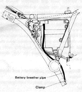
2. Always make sure the connections are correst when installing the battery. Make sure the breather pipe is properly connected, properly routed, and is not damaged or obstructed.
CAUTION:
The battery must be charged before using to insure maximum performance. Failure to properly charge the battery before first use, or low electrolyte level will cause premature failure of the battery. Charging current: 1.2 amps/10 hrs or until the specific gravity reaches 1.280 at 20°C (68°F)
WARNING:Battery electrolyte is poisonous and dangerous, causing severe burns, etc. It contains sulfuric acid. Avoid contact with skin, eyes or clothing.
Antidote:
EXTERNAL-Flush with water.
INTERNAL—Drink large quantities of water or milk. Follow with milk of magnesia, beaten egg or vegetable oil. Call physician immediately.
Eyes:
Flush with water for 15 minutes and get prompt medical attention. Batteries produce explosive gases. Keep sparks, flame, cigarettes, etc. away. Ventilate when charging or using in closed space. Always shield eyes when working near batteries. KEEP OUT OF REACH OF CHILDREN.
Headlight and Taillight
Headlight and TaillightHeadlight
1. Headlight bulb replacement

a. Remove the cowling assembly.

b. Remove the 2 screws holding the light unit assembly to the headlight body.

c. Disconnect the lead wires and remove the light unit assembly.

d. Remove the top and bottom fitting screws and the horizontal adjusting screw. Remove the light unit assembly from the headlight rim.

e. Remove the sealed beam unit holding screws. Remove the unit retaining ring and the defective unit.
f. Slip a new sealed beam unit into position and secure it with the retaining ring and install it into the headlight rim.
g. Reinstall the light unit assembly to the headlight body. Adjust the hedalight beam.
h. Reinstall the cowling assembly.
2. Headlight beam adjustment
a. Horizontal the beam to the right, turn the adjusting screw clockwise. To adjust the beam to the left, turn the screw counterclockwise.
b. Vertical adjustment:
Loosen the adjusting screw under the headlight body. Adjust vertically by moving the headlight body. When proper adjustment is determined, retighten the adjusting screw.

a. Horizontal adjusting screw
b. Vertical adjusting screw
Taillight
1. Taillight bulb replacement
a. Open the seat.
b. Pull open the lid in the seat cowl.
c. To remove the bulb, turn it approxi matety 30° counterclockwise.

1.Lid 2. Bulb
d. To install the bulb, reverse the removal procedure.
Spark Plug
Spark Plug1. Check the electrode condition and wear, insulator color and electrode gap.
2. Use a wire gauge for measuring the plug gap.
3. If the electrodes become too worn, replace the spark plug.
4. When installing the plug, always clean the gasket surface. Wipe off any grime that might be present on the surface of the spark plug, and torque the spark plug properly.
Standard spark plug: D8EA (NGK) or X24ES-U (ND)
Spark plug gap: 0.6-0.7 mm (0.024 ~ 0.028 in)
Spark plug tightening torque: 2.0 m-kg (14.5 ft-lb)
Engine
EngineAir Cleaner
Air Cleaner1. Removal
a. Open the seat.
b. Remove the side cover (left).
c. Remove the air cleaner case cover by removing the four screws.

d. Pull out the element.

I. Air filter element
2. Cleaning method
Tap the element lightly to remove most of the dust and dirt; then blow out the remaining dirt with compressed air from the inner surface of the element. If element is damaged, replace it.
3. Reassemble by reversing the removal procedure. Check whether the element is seated completely against the case.
4. The air cleaner element should be cleaned at the specified intervals.
CAUTION:
The engine should never be run without the air cleaner element installed; excessive piston and/or cylinder wear may result.
Cam Chain Adjustment
Cam Chain AdjustmentThe cam chain becomes stretched with use, resulting in improper valve timing and engine noise. To prevent this, the cam chain ten-sioner must be adjusted regularly.
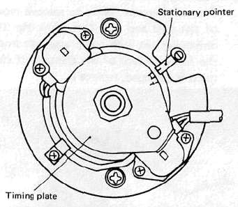
1. Remove the timing plate cover.
2. Slowly rotate the crankshaft counterclockwise until the "C" mark on the timing plate aligns with the stationary pointer.

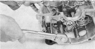
3. Loosen the tensioner lock nut and then loosen the stopper bolt. This releases the cam chain tensioner with the proper tension.

1. Lock nut 2. Stopper bolt
4. Tighten the stopper bolt and lock nut.
Stopper bolt torque: 0.6 m-kg (4.3 ft-lb) Lock nut torque: 0.9 m-kg (6.5 ft-lb)
5. Reinstall the timing plate cover.
Carburetor
CarburetorNOTE:
The carburetors are numbered 1, 2, 3, and 4 from the left when viewed from astride the motorcycle.
1. Idle mixture
The idle mixture is set at the factory by the use of special equipment. No attempt should be made by the dealer to change this adjustment.
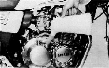
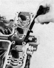
2. Synchronization
The seat must be opened and the rear of the tank elevated to gain access to the vacuum connections and synchronizing screw of the carburetors.
NOTE:
The valve clearances must be set properly before synchronizing the carburetors.
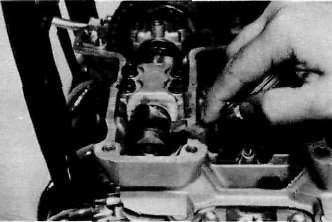
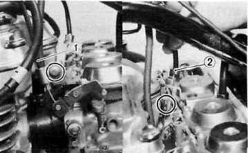
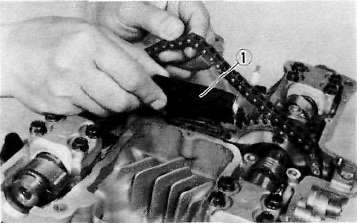
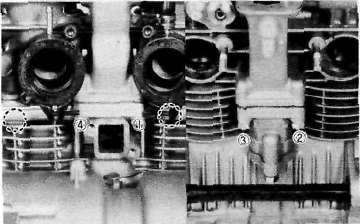
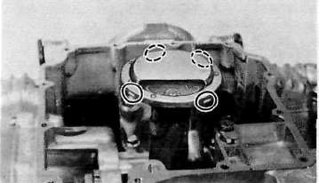
a. Remove the vacuum pipe from the carburetor manifold (No. 2 cylinder) and turn the fuel petcock to "PRI".
b. Remove the rubber caps from the No. 1, 3, and 4 carburetor manifolds.
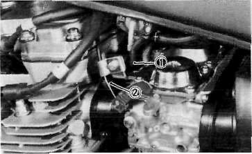
1, Vacuum pipe 2. Rubber cap
c. Remove either the left or right (but not both) blind plug at the end of the YICS (Yamaha Induction Control System) passage in the cylinder.
d. Insert the YICS shutoff tool (special tool) fully and flip the locking lever.
e. Connect each vacuum gauge hose to its proper carburetor.

1. Vacuum gauge
f. Start the engine allow it to warm-up for a few minutes. The warm-up is complete when engine responds normally to the throttle opening.
g. Make sure the engine idle speed is 1,000 ~~ 1,100 r/min. If it does not, adjust the idle speed with the throttle stop screw.
NOTE:
With the YICS shutoff tool fitted, the engine speed generally drops a little. Thus, continue with the following steps at idle speed of 1,000~ 1,100 r/min.
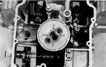
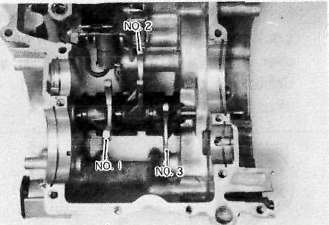
h. Each gauge reading will indicate the same if the carburetors are synchronized. The No. 3 carburetor has no synchronizing screw and the other carburetors are to be synchronized to it in order, one at a time.
First, synchronize carburetor No. 1 to carburetor No. 2 by turning the No. 1 synchronizing screw until both gauges read the same.
Second, in the same way synchronize carburetor No. 4 to carburetor No. 3. Third, by adjusting No. 2 screw to watch No. 3 carburetor reading, No. 1 and No.2 carburetors will both change to match No. 3 carburetor.

1. Synchronizing screws
i. Make sure that the engine now develops an idle engine speed of 1,000 ~ 1,100 r/min. If it does not, adjust the idle speed with the throttle stop screw and repeat the steps starting with g.
j. Remove the YICS shutoff tool and reinstall the blind plug.
Tightening torque:
2.2m-kg (16.0ft-lb)
3. Idle speed adjustment
NOTE:
Carburetors must be synchronized before setting final idle speed. The idle speed adjustment is made by turning only one throttle stop screw.
a. The engine must be warmed up before setting idle speed.
b. Set the engine idle speed by turning the throttle stop screw in (to increase engine speed) or out (to decrease engine speed).
Standard idle speed: 1,200 r/min

1. Throltle stop screw
Clutch Adjustment
Clutch AdjustmentFree play adjustment
a. Loosen either the handlebar lever adjuster lock nut or the cable length adjuster lock nut.
b. Turn the cable length adjuster either in or out until proper lever free play is achieved.
Clutch lever free play:
2 - 3mm (0.08 ~ 0.12 in)
1, Lock nut 2. Adjuster a. 2 — 3 mm (0.08— 0.12 \n)

1. Lock nut 2. Adjuster
Compression
CompressionInsufficient compression pressure will result in performance loss and may indicate leaking valves or worn or damaged piston rings. Procedure:
1. Make sure the valve clearance is correct.
2. Warm up the engine 2^3 minutes.
3. Remove all the spark plugs.
4. Install a compression check gauge.
5. Turn over the engine with the electric starter (make sure the battery is fully charged) with the throttle wide open until the pressure indicated on the gauge does not increase further.
Compression pressure (at sea level):
Standard ............ 8.5 kg/cm2(121 psi)
Minimum............ 7.0 kg/cm2(100 psi)
Maximum .......... 9.5 kg/cm2(135 psi)
WARNING:
When cranking the engine, ground the removed spark plug wires to prevent sparking.

1. Compression gauge
6. If the pressure is too low, squirt a few drops of oil into the cylinder being measured. Measure compression again. If there is a higher reading than before (without oil), the piston rings may be worn or damaged. If the pressure remains the same after measuring with the oil, either or both the rings and valves may be the cause.
7. Check each cylinder. Compression pressure should not vary more than specified value from one cylinder to any other cylinder.
Difference in gauge reading: Less than 1 kg/cm2 (14 psi)
Engine Oil
Engine Oil1. Oil level measurement a. Place the motorcycle on the center stand, Warm up the engine for several minutes.
NOTE:
Be sure the motorcycle is positioned straight up when checking the oil level; a slight tilt toward the side can produce false readings.
b. With the engine stopped, check the oil level through the level window located at the lower part of the right side crank-case cover.
NOTE:
Wait a few minutes until the oil level settles before checking.

1. Maximum mark 2- Minimum mark 3. Level window
c. The oil level should be between maximum and minimum marks. If the level is lower add sufficient oil to raise it to the proper level.
2. Engine oil and oil filter replacement
a. Start the engine and stop it after a few minutes of warm-up.
b. Place an oil pan under the engine and remove the oil filler cap.
c. Remove the engine drain plug and drain the oil.

1. Engine drain plug
d. Remove the oil filter bolt and filter element.

1. Oil filter cover
e. Re-install the drain plug (make sure it is tight).
Drain plug torque: 4.3 m-kg (31.0 ft-lb)
f. Install the new oil filter element, new "O-ring" and filter cover, and tighten the oil filter bolt.
Oil filter bolt torque: 1.5 m-kg (11.0 ft-lb)
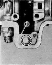
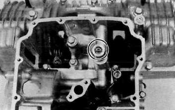
NOTE:
When installing the filter cover, make sure the "O-ring" is positioned properly and insert the locating projection on it into the corresponding guides on the crankcase.

1. Proper O-ring position
g. Add oil through the oil filler hole.
CAUTION:
Take care not to allow foreign material to enter the crankcase.
Periodic oil change: 2.2 lit (2.3 US qt.)
With oil filler replacement: 2.5 lit (2.6 US qt.)
Recommended oil:

h. After replacement of the engine oil and/ or oil filter, be sure to check for oil leakage. The oil level indicator light should go off after the engine has started.
CAUTION:
If the indicator light flickers or remains on, the oil level switch may be damaged. Refer to "CHAPTER 6" for corrective action.
Ignition Timing
Ignition Timing1. Ignition timing is checked with a timing light by observing the position of the stationary pointer and the marks stamped on the timing plate.
The timing plate is marked as follows:
"n"— Firing range for No. 1 (L.H.) cylinder
"T" ....Top Dead Center for No. 1 (L.H.) and No. 4 (R.H.) cylinders.
2. Connect the timing light to No. 1 (L.H.) spark plug lead wire.
3. Start the engine and keep the engine speed as specified. Use a tachometer to check the engine speed.
Specified engine speed: 1,200 r/min
4. The stationary pointer should be within the limits of " n " on the timing plate. If it exceeds the limits or does not steady, check the timing plate for tightness and/or ignition system for damage. (See "CHAPTER 6. ELECTRICAL)
CAUTION:
Never bend the stationary pointer.
Valve Clearance Adjustment
Valve Clearance AdjustmentA. Valve clearance adjustment
NOTE:
Valve clearance must be measured with the engine and at room temperature.
1. Open the seat and remove the fuel tank.
2. Remove the flasher relay and spark plug lead wires.

Remove the cylinder head cover and left crankcase cover (pick-up base cover). Care should be taken to not scratch or damage the gasket sealing surfaces. Turn the crankshaft with the nut on the left end of the crankshaft to turn the cams. The proper position of the cam when measuring the valve clearance is with the cam lobe directly opposite the valve lifter,

5. Insert a feeler gauge between the valve lifter and the camshaft base circle.
Intake valve clearance (cold):
0.11-0.15 mm (0.004-0.006in)
Exhaust valve clearance (cold):
0.16-0.20 mm (0.006-0.008 in)
Adjustment
Valve clearance is adjusted by replacing the adjusting pad on the top of the valve lifter. Adjusting pads are available in 25 thicknesses ranging from No. 200 (2.00 mm) to No. 320 (3.20 mm) in steps of 0.05 mm. The thickness of each pad is marked on the pad face that contacts the valve lifter (not the cam). Adjustment of the valve clearance is accomplished as follows:
1. Determine valve clearance (feeler gauge measurement.)
2. Remove adjusting pad and note number.
3. Selectproper pad from appropriate chart (intake or exhaust chart).
4. Install new pad and check installed clearance.
Procedure
1. Measure valve clearance. If clearance is incorrect, record the measured amount of clearance. This must be measured carefully.
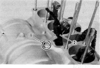
2. There is a slot in the valve lifter. This slot must be positioned opposite the blade of the tappet adjusting tool before the tool is installed.
3. Turn the cam until the lobe fully depresses the valve lifter and opens the valve. Install the tappet adjusting tool as shown tohold the lifter in this depressed position.
NOTE:
The tappet adjusting tool is fastened to the cylinder head securely using an alien screw. Make sure that the tool contacts the lifter only, and not the pad.
CAUTION:
If the cam lobe touches the tappet adjusting tool, the stress may fracture the cylinder head. DO NOT ALLOW THE CAM LOBE TO CONTACT THE TAPPET ADJUSTING TOOL.


1. Tappet adjusting tool 2. Adjusting pad
4. Carefully rotate the cam so that the pad can be removed. To avoid cam touching the adjusting tool, turn cams as follows: (view from left side of the motorcycle) Intake: Carefully rotate CLOCKWISE. Exhaust: Carefully rotate COUNTERCLOCKWISE.

5. Remove the pad from the lifter. There is a slot in the lifter. Use a small xrew-driver or other blade and tweezers or a magnetic rod to remove the pad. Note the number on the pad.

1. Adjusting pad
6 Proper pad selection is made as follows:
Chart lookup method:
Refer to the appropriate chart for exhaust or intake valves:
0.11 to 0.15mm required clearance (Intake side) chart
0.15 to 0.20mm required clearance (Exhaust side) chart
a. Find number of original (installed) pad number on chart. Read down on chart.
b. Find measured valve clearance (from step 1) on chart. Read across.
c. At the intersection of installed pad number (down) and measured clearance (across) is a new pad number.
EXAMPLE:
Intake valve, installed pad: No. 250 (read down)
Measured clearance:0.32 mm (read across)
New pad number: No. 270(intersection of down & across)
Alternate shim calculation method:
Since all shims come in .05mm (.002") increments, you can quickly calculate the required size without a chart.
If the measured clearance is within 0.05mm (0.002") of the required clearance, then no change is needed.
If the measured clearance greater than 0.05mm (0.002") but 0.10mm (0.004") or less different than the required clearance then the next size shim is required.
If the measured clearance greater than 0.10mm (0.004") but 0.15mm (0.006") or less different than the required clearance then the next size shim is required.
Clearances that are too small require thinner shims. Clearances that are too large require thicker shims.
Example: Required exhaust valve clearance is 0.16~0.20mm. Measured clearance is 0.12mm (gap too small). Installed shim is Y270. Required shim is one size thinner: Y265.
NOTE:
The new pad number is to be used as a guide only. Verify the correctness of this choice in the following step(s).
7. Install the new pad in the lifter. Install the pad with the number down.
8. Remove tappet adjusting tool,
9. Turn crankshaft to rotate cam several rotations. This will set the pad in the lifter.
10. Check valve clearance (step 3). If clearance is incorrect, repeat preceding steps until proper clearance is obtained.
11. Inspect head cover gasket. If bent or torn, replace gasket.
12. Reinstall removed parts in reverse order.
Alternate shim calculation method:
Since all shims come in .05mm (.002") increments, you can quickly calculate the required size without a chart.
If the measured clearance is within 0.05mm (0.002") of the required clearance, then no change is needed.
If the measured clearance greater than 0.05mm (0.002") but 0.10mm (0.004") or less different than the required clearance then the next size shim is required.
If the measured clearance greater than 0.10mm (0.004") but 0.15mm (0.006") or less different than the required clearance then the next size shim is required.
Clearances that are too small require thinner shims. Clearances that are too large require thicker shims.
Example: Required exhaust valve clearance is 0.16~0.20mm. Measured clearance is 0.12mm (gap too small). Installed shim is Y270. Required shim is one size thinner: Y265.
| Attachment | Size |
|---|---|
| 11-15mm_valve_shim_chart.xls | 20 KB |
| 16-20mm_valve_shim_chart.xls | 18.5 KB |
Chapter 3. Engine Overhauling
Chapter 3. Engine OverhaulingEngine Removal
Engine RemovalENGINE REMOVAL
NOTE:
It is not necessary to remove the engine in order to remove the cylinder head, cylinder, or pistons.
A. Preparation for removal
1. All dirt, mud, dust and foreign material should be thoroughly removed from the exterior of the engine before removal and disassembly. This will help prevent and harmful foreign material from engine oil.
2. Before the engine removal and disassembly, be sure that you have the proper tools and cleaning equipment so that you can perform a clean and efficient job.
3. During disassembly of the engine, clean and place all of the parts in trays in order of disassembly. This will speed up assembly time and help insure correct reinstall-action of all the engine parts.
4. Place the motorcycle on its center stand. Start the engine and allow it to warm up. Stop the engine and drain the engine oil.
5. Remove the oil filter cover from the crankcase.
6. Remove the left and right side covers.
B. Seat and fuel tank
1. Turn the fuel petcock to "ON".
2. Open the seat and the fuel tank holding bolt. Lift the rear end of the fuel tank and disconnect the fuel pipes and vacuum pipe from the petcock.
3. Disconnect the fuel level switch lead wire.
4. Remove the tool tray.
C. Mufflers
1. Remove the rear brake pedal and foot-rests (left and right).
2. Remove the exhaust pipe holding nuts from the cylinder head.

3. Loosen the clamp bolts securing the muffler joints.

4. Remove the bolts holding the right and left mufflers to the muffler bracket and remove the left and right mufflers.

D. Battery case
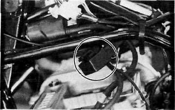
1. Remove the battery cover then remove the negative battery cable from the battery terminal. Remove the battery.
2. Remove the battery case holding bolts and remove the battery case.
NOTE:
The engine ground wire is secured together with left side holding bolt.

1. Engine ground wire
E. Air cleaner case
1. Remove the clamps holding the carburetors to the air cleaner case and intake manifolds. Remove the crankcase ventilation hose at the right crankcase cover.

1. Crankcase ventilation hose
2. Remove the bolts holding the air cleaner case to the frame.

3. Remove the starter (CHOKE) cable from the carburetor.
4. Remove the air cleaner joint rubbers and pull the carburetor assembly to the rear.
5. Disconnect the throttle cable from the carburetor throttle lever and remove the carburetor assembly to the right.
1. Starter (CHOKE) cable 2. Throttle cable
F. Wiring and cables
1. Disconnect the clutch cable at the crankcase side.

2. Remove the spark plug lead wires and the tachometer cable.

3. Disconnect the electric starter cable at the starter relay switch.
4. Disconnect the pick-up coil and A.C.G. lead wire couplers.
Position the disconnect lead wires so that they can be safely removed. See page .

CAUTION:
The A.C.Generator lead, starter cable, and pick-up lead are clamped at the lower cross tube of the frame. Do not forget the remove this clamp before removing the engine.
5. Remove the flasher relay.
G. Change pedal and drive sprocket
1. Remove the change pedal and left crank-case cover.
2. Loosen the drive sprocket securing bolts and remove the sprocket holder.
3. Remove the drive sprocket.

H. Engine removal
1. Remove the front engine mounting bolts and nuts. Remove the brackets.

NOTE:
It is advisable to hold the engine with a suitable garage jack before removing the engine mounting bolts and nuts.
2. Remove the rear engine mounting bolt.

3. Slide the engine forward slightly and remove the engine to the right.
NOTE:
Position a box or other support to the right side of the motorcycle for the assistance when removing the engine.
Disassembly
DisassemblyCylinder and Cylinder head removal
Cylinder and Cylinder head removal1. Remove the cylinder head cover.
2. Remove the left crankcase cover (pickup coil cover).
3. Remove the cam chain tensioner.

Use a 19 mm wrench on the timing plate flats to rotate the crankshaft counterclockwise until the engine is at T.D.C.
CAUTION:
Never use an alien wrench to rotate the crankshaft. Always use the 19 mm flats provided on the timing plate to rotate this engine.
5. Remove the center cam shaft caps. Next, remove the four cam sprocket bolts.
6. Slip each sprocket off its mounting boss on the cam.
CAUTION:
From this point on, do not rotate the cam shaft or valve damage may occur. On this, it is not necessary to break the cam chain. However, it can be broken if so desired. It is easier to disassemble the engine without separating the chain.
7. Remove the cam chain guide.
1. Cam chain guide
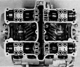
8. Remove the cam caps. Note the location of the cam caps. The caps for the intake camshaft are identified 1-1 through I-4. The exhaust cam caps are identified E-1 through E-4. Directional arrows are cast on each cap and point toward the clutch side.
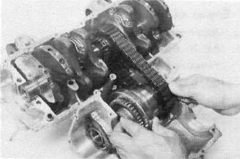
9. Fasten safety wire to the cam chain to prevent itsfalling into the crankcase cavity.
Slide the cams and sprockets from under the chain andremove the cams and sprockets.

10. Remove the cam chain guide securing boltand lock nut. Remove the front cam chain guide.
1. Lock washer 2. Front cam chain guide
11. Remove the spark plugs.
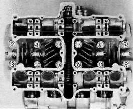
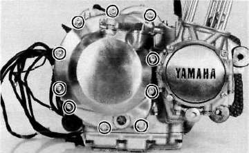
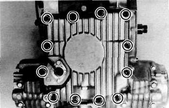
12. Remove the cylinder head bolts and nuts in the numerical order as shown. Start by loosening each nut 1/2 turn until all of the nuts are loose. Remove the cylinder head.
13. Remove the front cylinder holding nut and remove the cylinder assembly. It may be necessary to tap the cylinder lightly to loosen it from the base gasket.
14. Remove the rear cam chain guide by loosening the holding bolt.
1. Holding bolt 2. Rear cam chain guide
Cylinder head and Piston Disassembly
Cylinder head and Piston DisassemblyCylinder head disassembly
1. Remove the valve lifters and pads. Be careful not to scratch the lifter bodies or lifter bores in the cylinder head. Be very careful to identify each lifters position so that it may be returned to its original place.

1. Valve filter 2. Adjusting pad
2. Mount the valve spring compressor on the head and depress each valve spring. Take out the retainer and valve spring with tweezers.

1. Valve spring compressor
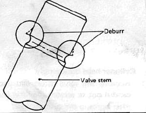
3. Remove valves.
NOTE:
Deburr any deformed valve stem end. Use an oil stone to smooth the stem end. This will help prevent damage to the valve guide during valve removal.
4. Use a small box to hold the parts and identify the original position of each lifter and valve. Be very careful not to mix the location of these components.

C. Piston
1. Make each piston to aid in reassembly.
2. Place a clean towel or rag into the crank-case to keep circlips and material from falling into the engine.
3. Remove piston pin clips, piston pins, and pistons.

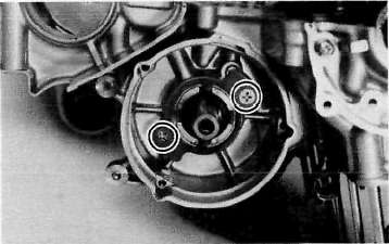
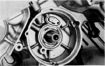
Pick-up coil, Generator and Starter
Pick-up coil, Generator and StarterPick-up coil assembly
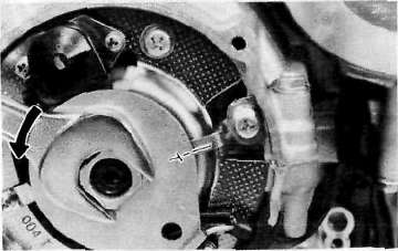
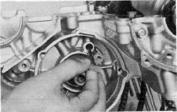
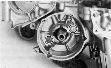
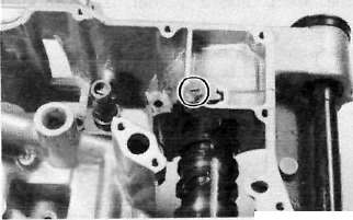
1. Remove the alien bolt that holds the timing plate.
2. Remove the pick-up coil securing screws and remove the pick-up coil assembly.

Generator and starter motor
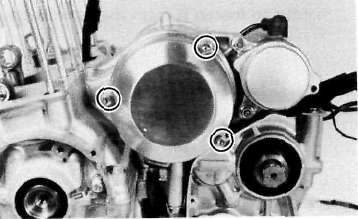
1. Remove the generator cover and stator coil assembly.
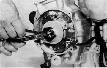
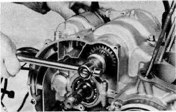
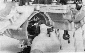
2. Install the rotor holding tool (special tool) on the rotor as shown and remove the rotor holding bolt.
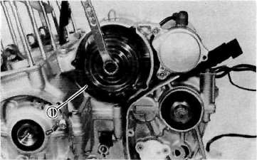
1. Rotor holding tool
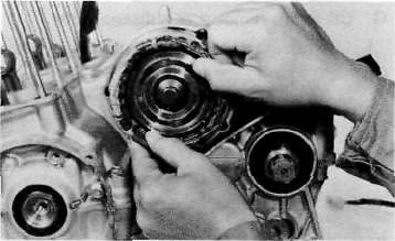
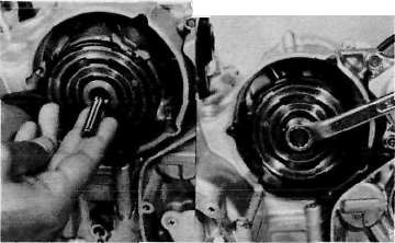
3. Install the holding tool as shown and insert the rotor puller adapter (special tool) into the rotor shaft and screw in the rotor puller (special tool). Remove the rotor.
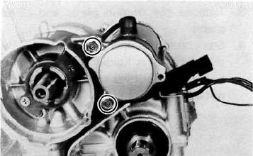
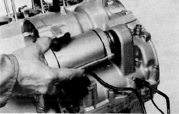
4. Remove the starter motor securing bolts and remove the motor assembly,
Clutch and Oil Pump
Clutch and Oil PumpClutch
1. Remove right crankcase cover.
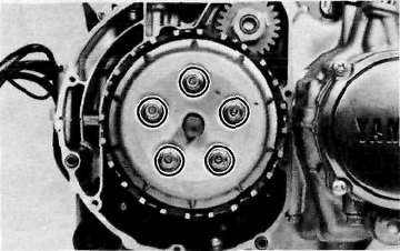
2. Release the tension evenly on the 6 mm bolts and remove the clutch pressure plate and clutch springs.
3. Remove the friction plates and clutch plates.
4. Straighten the lock washer tab. Use the clutch boss holder (special tool) to hold the clutch boss and remove the lock nut and lock washer.
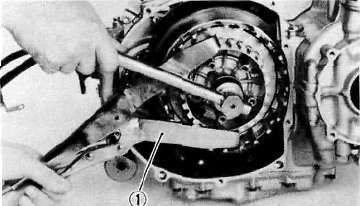
1. Clutch boss holder
5. Remove the clutch boss and thrust plate.
6. Remove the primary driven gear assembly.
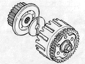
7. Remove the primary drive gear and collar.
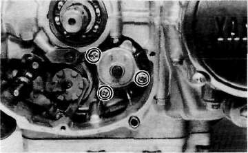
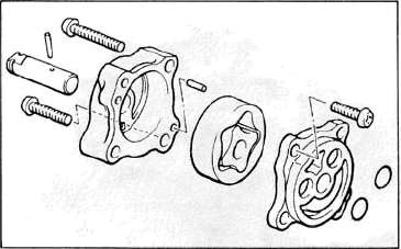
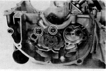
Oil pump removal and disassembly
1. Remove the oil pump driven sprocket.
2. Remove the oil pump securing screws and remove the oil pump assembly.
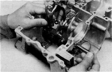
3. Remove the shift lever assembly.
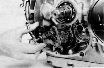
1. Shift lever assembly
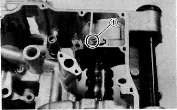
4. Remove the strainer cover. Note the wire harness clip position.
5. Remove the strainer screen, strainer housing and the relief valve.
CAUTION:
Do not attempt to remove the strainer screen as it is permanently fitted onto the pump housing. If the pump housing and/or any parts of the pump are damaged, the pump assembly must be replaced with a new one.
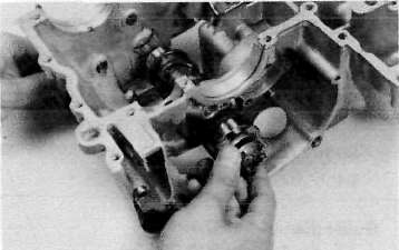
6. Remove the oil pump cover and rotor assembly.
7. Remove the pressure relief valve spring and plunger.
Crankcase
CrankcaseCrankcase disassembly
1. Remove the right-front crankcase cover.
2. Remove the upper crankcase bolts, starting the highest numbered bolt.
Turn over the engine and remove the lower crankcase bolts.
CRANKCASE TIGHTENING SEQUENCE

LOWERCASE
UPPERCASE
*6 mm
3. Separate the lower case from the engine. Use a soft rubber hammer to carefully separate the crankcase.
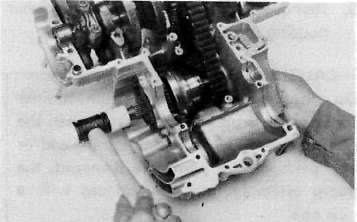
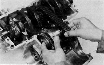
I. Upper crankcase
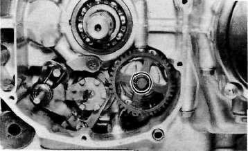
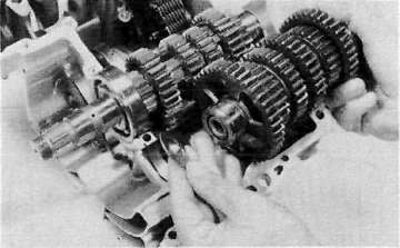
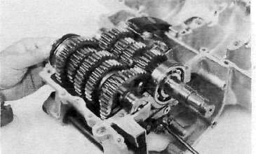
1. Remove the transmission assembly.
2. Remove the A.C.G. shaft cover.
3. Remove the oil spray nozzle.
4. Carefully remove the A.C.G. shaft from the gear.
5. Remove the gear from the chain.
6. Straighten the lock washer tab and remove the bolt securing the starter idle gear shaft. Remove the shaft and starter idle gear.
J. Lower crankcase
1. Remove the dowel pin and "O-ring".
2. Remove the shift bar stopper securing screw and bolt.
3. Remove the shift fork guide bar and shift forks. The shift forks are identified by numbers cast on their sides.
4. Remove the neutral switch.
5. Remove the bolt securing the shift cam locating pin and remove the stopper plate and locating pin.
1. Shift cam locating pin
6. Pull out the shift cam.
7. Remove the HY-VO chain tensioner and chain guide.
Inspection and Repair
Inspection and RepairCylinder head and Cylinder
Cylinder head and CylinderCylinder head cover
Place head cover on a surface plate. There should be no warpage. Correct by re-surfacing as follows:
Place #400 or #600 grit wet sandpaper on surface plate and re-surface head cover using a figure-eight sanding pattern. Rotate head cover several times to avoid removing too much material from one side.
Cylinder head
1. Using a rounded scraper, remove carbon deposits from combustion chamber. Take care to avoid damaging spark plug threads and valve seats. Do not use a sharp instrument. Avoid scratching the aluminum.
2. Check the cylinder head warpage with a straight edge as shown.

The warpage should not exceed the specified limit, if necessary resurface. If the warpage exceeds allowable limit, the cylinder head should be replaced with a new one.
Cylinder head warpage: less than 0.05 mm (0.002 in)
Allowable limit: 0.25 mm (0.010 in)
Camshaft, chain and sprockets
Camshaft, chain and sprockets1. Camshaft
a. The cam lobe metal surface may have a blue discoloration due to excessive friction. The metal surface could also start to flake off or become pitted.
b. If any of the above wear conditions are readily visible, the camshaft should be replaced.
c. Even though the cam lobe surface appears to be in satisfactory condition, the lobes should be measured with a micrometer. Cam lobe wear can occur without scarring the surface. If this wear exceeds a pre-determined amount, valve timing and lift are affected. Replace the camshaft if wear exceeds the limits.
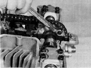
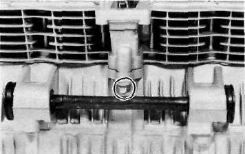
d. Install the camshaft on the cylinder head. Place a strip of Plastigage between camshaft and camshaft cap as illustrated (lengthwise along camshaft). Tighten the nuts with specified torque. Remove the camshaft cap and determine the clearance by measuring the width of the flattened Plastigage.

1. Plastigage
NOTE:
Do not turn camshaft when measuring clearance with Plastigage.
Camshaft-to-cap clearance:
Standard: 0.020 ~ 0.054 mm (0.0008-0.0021 in)
Maximum: 0.160 mm (0.006 in)
If the camshaft-to-cap clearance exceeds specification, measure camshaft bearing surface diameter.
Bearing surface diameter:
Standard: 24.967 ~ 24.980 mm (0.9830- 0.9835 in)
1) If camshaft diameter is less than specification, causing excessive clearance, replace camshaft.
2) If camshaft is within specification and camshaft-to-cap clearance is excessive, replace cylinder head.
2. Cam chain
Except in cases of oil starvation, the cam chain wears very little. If the cam chain has stretched excessively and it is difficult to keep the proper cam chain tension, the chain should be replaced.
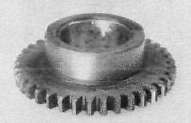
3. Cam sprockets
Check cam sprockets for obvious wear.
4. Cam chain dampers and tensioner
Inspect the top cam chain damper (stopper guide) and two (2) vertical (slipper-type) dampers for excessive wear. Any that shows excessive wear should be replaced. Worn dampers may indicate an improperly adjusted or worn-out cam chain.
F. Cylinder
1. Inspect the cylinder walls for scratches. If vertical scratches are evident, the cylinder wall should be rebored or the cylinder should be replaced.
2. Measure cylinder wall wear as shown. If wear is excessive, compression pressure will decrease. Rebore the cylinder wall and replace the piston and piston rings. Cylinder wear should be measured at three depths with a cylinder bore gauge. (See illustration.)
Cap nut tightening torque: 1.0nvkg(7.2ft-ib)
|
|
Standard |
Wear Limit |
|
Cylinder bore |
57.00 mm (2.244 in) |
57.10 mm (2.248 in) |
|
Cylinder taper |
- |
0.05 mm (0.002 in) |
|
Cylinder out-of-round |
0.01 mm (0.0004 in) |

If the cylinder wall is worn more than the wear limit, it should be rebored.
Valve, Guide and Seat
Valve, Guide and SeatValve, valve guide, and valve seat
1. Check the valve face and the stem end for wear. If the valve face and/or the stem end are pitted or worn, regrind the valve with a valve refacer. Replace the valve if any dimension exceeds the specifications in the illustration.

Intake/Exhaust valve
Minimum thickness (Service limit) 0.7 mm (0.028
Minimum length (Service limit) 4.0 mm (0.157 in)
2. Valve stem wear must be measured and then combined with valve guide measurements to guide clearance. This clearance must be within tolerances. If it exceeds the maximum limit, then replace either or both valve and guide, as necessary.
|
Valve Stem Clearance |
Maximum |
|
|
Intake |
0.010 ~ 0.037 mm (0.004 -0.0015 in) |
0.10 mm (0.004 in} |
|
Exhaust |
0.025 ~ 0.052 mm (0.0010-0.0020 in) |
0.12 mm (0.005 in) |
3. Valve stem end
Inspect the end of the valve stem. If the end appears to be "mushroomed" or has a larger diameter than the rest of the stem, the valve, valve guide, and oil seal should be replaced.
4. Turn valve on "V" blocks and measure the amount of stem runout with a dial guage. If it exceeds the maximum limit, replace the valve.
Maximum valve stem runout: 0.03 mm (0.0012 in)

5. Valve guide and valve oil seal replacement If oil leaks into the cylinder through a valve due to a worn valve guide, or if a valve is replaced, the valve guide should also be replaced.
NOTE:
The valve oil seal should be replaced whenever a valve is removed or replaced.
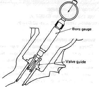
a. Measure valve guide inside diameter with a small bore gauge. If it exceeds the limit, replace with an oversize valve guide.
Guide diameter (I.D.): Limit: 6.10 mm (0.240 in!
b. To ease guide removal and reinstallation, and to maintain the correct interference fit, heat the head to 100°C (212°F). Use an oven to avoid any possibility of head warpage due to uneven heating.
c. Use the appropriate shouldered punch (special tool) to drive the old guide out and drive the new guide in,
NOTE:
When a valve guide is replaced, the O-ring should also be replaced.

1. Valve guide installer
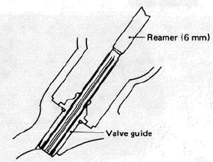
d. After installing the valve guide, use the 6 mm reamer (special tool) to obtain the proper valve guide to valve stem clearance.
e. After installing the valve guide in the cylinder head, the valve seat must be recut. The valve should be lapped to the new seat.
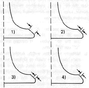
6. Grinding the Valve Seat
a. The valve seat is subject to severe wear. Whenever the valve is replaced or the
valve face is re-surfaced (see caution) The valve seat should be re-surfaced at a 45° angle. If a new vlave guide has been installed the valve seat must be recut to guarantee complete sealing between the valve face and seat.

CAUTION:
If the valve seat is obviously pitted or worn, it should be cleaned with a valve seat cutter. Use the 45° cutter, and when twisting the cutter, keep an even downward pressure to prevent chatter marks.
If cutting section "A" of the valve seat, use 30° cutter. If cutting section "B", use the 45° cutter. If cutting section "C" use 60° cutter. b. Measure valve seat width. Apply mechanic's bluing dye (such as Dykem) to the valve face and valve seat, apply a very small amount of fine grinding compound around the surface of the valve face insert the valve into position, and spin the valve quickly back and forth. Lift the valve, clean off all grinding compound, and check valve seat width. The valve seat and valve face will have removed bluing wherever they contacted each other. Measure the seat width with vernier calipers. It should measure approximately 1.1 mm (0.0433 in). Also, the seat should be uniform in contact area. If valve seat width varies, or if pits still exist, further cutting will be necessary. Remove just enough material to achieve a satisfactory seat.
|
Standard Width |
Wear Limit |
|
|
Seat width |
1.0* 0.1 mm (0.0394 ±0.0039 in) |
2.0 mm (0.080 in) |

1. Valve guide remover

a. Seat width
c. If the valve seat is uniform around the perimeter of the valve face, but is too wide or not centered on the valve face, it must be altered. Use either the 30°, 45° or 60° cutters to correct the improper seat location in the manner described
1) If the valve face shows that the valve seat is centered on the valve face, but too wide, then lightly use both the 30° and the 60° cutters to reduce the seat width to 1.1 mm (0.0433 in).

1. Valve seat cutter
2) If the seat shows to be in the middle of the valve face, but too narrow, use the 45° cutter until the width equals 1.1 mm (0.0433 in).
3) If the seat istoo narrow and right up near the valve margin, then first use the 30° cutter and then the 45° cutter to get the correct seat width.
4) If the seat is too narrow and down near the bottom edge of the valve face, then first use the 60° cutter and then the 45° cutter.
7. Lapping the valve/valve seat assembly
a. The valve/valve seat assembly should be lapped if neither the seat nor the valve face are severely worn.
b. Apply a small amount of coarse lapping compound to valve face. Insert the valve into the head. Rotate the valve until the valve and valve seat are evenly polished. Clean off the coarse compound, then follow the same procedure with fine compound.
Continue lapping until the valve face shows a complete and smooth surface all the way around. Clean off the compound material. Apply bluing dye to the valve face and seat and rotate the valve face for full seat contact which is indicated by a grey surface all around the valve face where the bluing has been rubbed awav.

Valve leakage check
After all work has been performed on the valve and valve seat, and all head parts have been assembled, check for proper valve/valve seat sealing by pouring solvent into each of the intake ports, then the exhaust ports. There should be no leakage past the seat. If fluid leaks, disassemble and continue to lap with fine lapping compound. Clean all parts thoroughly, reassemble and check again with solvent. Repeat this procedure as often as necessary to obtain a satisfactory seal.
Valve spring and lifters
Valve spring and lifters1. Checking the valve springs
a. This engine uses two springs of different sizes to prevent valve float or surging. The valve spring specifications show the basic value characteristics.
b. Even though the spring is constructed of durable spring steel, it gradually loses some of it's tension. This is evidenced by a gradual shortening of free length. Use a vernier caliper to measure spring free length. If the free length of any spring has decreased more than 2 mm (0.080 in) from its specification replace it.

c. Another symptom of a fatigued spring is insufficient spring pressure when compressed. This can be checked using a valve spring compression rate gauge. Test each spring individually. Place it in the gauge and compress the spring first to the specified compressed length with the valve closed (all spring specifications can be found in the previous section, Valve Spring), then to the length with the valve open. Note the poundage indicated on the scale at each setting. Use this procedure with the outer springs, then the inner springs.

NOTE:
All valve springs must be installed with larger pitch upward as shown.
|
Valve Spring Specifications |
||
|
OUTER |
INNER |
|
|
Free length |
37.2 mm 0.465 in) |
35.5 mm (1.398 in) |
|
Installed length (valve closed) |
32.0 mm (1.260 in) |
30.5 mm (1.201 in) |
|
Installed pressure |
18.5 kg (40.8 lb) |
9.3 kg (20.5 lb) |
|
Allowable tilt from vertical |
2.6° |
4- |
2. Valve lifter
a. Check each valve lifter for scratches or other damage. If the lifter is damaged in any way, the cylinder head surface in which it rides is probably also damaged. If the damage is severe, it may be necessary to replace both the lifter and the cylinder head.
NOTE:
For proper valve lifter-to-head clearance, always install lifters on their original valves.
Piston, rings and pin
Piston, rings and pin
Piston
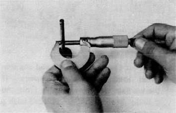
a. Measure the outside diameter of the piston at the piston skirt. Measurement should be made at a point 7.5 mm (0.3 in) above the bottom edge of the piston. Place the micrometer at right angles to the piston pin.
|
Standard |
57.00 mm (2.244 in) |
|
|
Oversize 1 |
57.25 mm (2.254 in) |
|
|
Oversize 2 |
57.50 mm (2.264 in) |
|
|
Oversize 3 |
57.75 mm (2.274 in) |
|
|
Oversize 4 |
58.00 mm (2.284 in) |

a. 7.0 mm (0.28 in)
b. Determine piston clearance as follows:
Minimum bore measurement - Maximum piston measurement = Piston clearance
EXAMPLE:
57.00 mm (2.2440 in) - 56.96 mm (2.2424 in) = 0.04 mm (0.0016 in)
Piston clearance
|
Piston clearance: |
|
|
Standard: |
0.025-0.045 mm |
|
(0.0010 - 0.0018 in) |
|
|
Service limit: |
0.1 mm (0.0039 in) |
c. Piston ring/ring groove fit must have correct clearance. If the piston and ring have already been used, the ring must be removed and the ring groove cleaned of carbon. The ring should then be reinstalled. Use a feeler gauge to measure the gap between the ring and the land.
|
Side clearance |
Top |
0.03-0.07 mm (0.0012-0.0028 in) |
|
2nd |
0.02 -0.06 mm (0.0008 -0.0024 in) |

1. Feeler gauge
Piston ring
a. The oversize top and middle ring sizes are stamped on top of the ring.
|
Oversize 1 |
0.25 mm (0.0098 in) |
|
Oversize 2 |
0.50 mm (0.0197 in) |
|
Oversize 3 |
0.75 mm (0.0295 in) |
|
Oversize 4 |
1.00 mm (0.0394 in) |
b. The expander spacer of the bottom ring (oil control ring) is color-coded to identify sizes.
The color mark is painted on the expander spacer.
|
Size |
Color |
|
Oversize 1 |
Brown |
|
Oversize 2 |
Blue |
|
Oversize 3 |
Black |
|
Oversize 4 |
Yellow |
c. Push the ring into the bore and check end gap clearance with a feeler gauge.
NOTE:
The end gap on the expander spacer of the oil control ring is unmeasurable. If the oil control ring rails show excessive gap, all three components should be replaced.
|
Standard |
Limit |
|
|
Top/2nd ring |
0.15~0.35 mm (0.006-0.014 in) |
1.0 mm (0.039 in} |
|
Oil control (Rails) |
0.3 -0.9 mm (0.012^0.035 in) |
1.5 mm (0.059 in) |
Piston pin
1. Apply a light film of oil to pin. Install in connecting rod small end. Check for play. There should be no noticeable vertical play. If play exists, check connecting rod small end for wear. Replace pin and connecting rod as required.
2. The piston pin should have no noticeable free play in piston. If the piston pin is loose, replace the pin and/or the piston.
Crankshaft
Crankshaft1. Crankshaft run-out
Support the crankshaft at both ends on V-blocks. Measure the amount of crankshaft run-out on the main bearing journals with a dial gauge while rotating crankshaft.
Run-out limit: 0.03 mm (0.0012 in)
If run-out exceeds limit, replace crankshaft.

2. Inspection of bearings
Check the bearings. If the inner or outer surface is burned,flaked, rough, scratched or worn, the bearings should be replaced.
3. Measuring main bearing oil clearance
a. Clean all crankshaft and crankcase journal surfaces.
b. Place upper crankcase half upside-down on a bench. Install bearing inserts into top crankcase.
c. Install crankshaft into upper crankcase.
d. Place Plastigage on crankshaft journal surface to be inspected.
NOTE:
Do not move crankshaft until clearance check has been completed.
e. Install bearings into bottom crankcase. Carefully, place lower crankcase onto upper crankcase.
f. Install crankcase holding bolts 1 through 10. Tighten to full torque in torque sequence cast on crankcase.
Crankcase torque (8 mm bolt): 2.4 m-kg (17.5 ft-lb)
g. Remove bolts in reverse assembly order (10, 9, 8...etc.)
h. Carefully remove lower crankcase. Measure width of Plastigage on crankshaft journals to determine clearance.
Main bearing oil clearance: 0.040- 0.064 mm (0.0016- 0.0025 in)

1. Plasligage
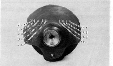
4. Crankshaft main bearing and connecting rod bearing selection
a. Numbers used to indicate crankshaft journal sizes are stamped on the L.H. crankweb. The first five (5) are main bearing journal numbers, starting with the left journal. The four (4) rod bearing journal numbers follow in the same sequence.
The upper crankcase half is numbered 4, 5, or 6 as shown.


b. The connecting rods are numbered 4 or 5. The numbers for rods are stamped with ink on the rod itself.

1. Connecting rod size number
c. The proper bearing selection is made by subtracting the crankshaft journal number from the crankcase or rod size number. Use the color code to choose the proper bearing.
EXAMPLE:
Rod No. (Minus) Journal No. = Bearing No.
5-2 = 3 No. 3 bearing is Brown. Use Brown bearing inserts.
|
BEARING COLOR CODE |
|
|
No. 1 |
Blue |
|
No. 2 |
Black |
|
No. 3 |
Brown |
|
No. 4 |
Green |
|
"No. 5 |
Yellow |
For crankshaft main bearing only.
d. When assembling, apply a liberal coat of motor oil to all bearing surfaces.
NOTE:
When applying final torque to the rod caps, observe the following procedures:
e. Apply molybdenum disulfide grease to connecting rod bolt threads. Apply torque evenly to both ends of the cap. While tightening, if a torque of 2.0 m-kg (14.5 ft-lb) or more is reached, DO NOT STOP tightening until final torque is reached. If tightening is interrupted between 2.0 m-kg and 2.5 m-kg, loosen the nut to less than 2.0 m-kg and start again. Tighten to full torque specification without pausing.
Oil Pump and Clutch
Oil Pump and ClutchOil pump
1. Check the clearance between housing and outer rotor.
Standard clearance:
0.09 ~ 0.15 mm (0.0035 ~ 0.0059 in)
2. Check the clearance between outer rotor and inner rotor.
Standard clearance: 0.03 ~ 0.09 mm (0.0012 ~ 0.0035 in)
3. Check the plunger for scrathces and wear.
Clutch
1. Clutch housing
a. Check the dogs on the clutch housing.
Look for cracks and signs of galling on
edges. If damage is moderate, deburr.
If severe, replace the clutch housing.
NOTE:
Galling on the friction plate dogs of the clutch housing will cause erratic clutch operation.

b. Check the clutch housing bearing for
damage. If damaged replace bearing. 2. Clutch boss
a. The clutch boss contains a built-in damper beneath the first clutch plate (clutch plate 2). It is not normally necessary to remove the circlip and disassemble the built-in damper unless there is serious clutch chattering.
b. Check splines on clutch boss for galling. If damage is slight to moderate, deburr; if it is severe, replace clutch boss.
NOTE:
Galling on clutch plate splines will cause erratic operation.

3. Friction and clutch plates
Check clutch steel plates and friction plates for heat damage. Measure friction plate thickness at 3 or 4 points. Measure clutch plates for warpage with a dial gauge and stand. Replace clutch plate or friction plates as a set if any is faulty or beyond wear limits.
|
|
Standard Wear limit |
|
|
Friction plate thickness |
3.0 mm (0.12 in) |
2.8 mm (0.11 in) |
|
Clutch plate warp limit |
- |
0.15 mm (0.006 in) |


1. Feeler gauge
4. Clutch actuating mechanism

1. Plate washer 2. Thrust bearing 3. Pull rod
a. Check the pull rod rack gear teeth for wear and damage, replace if damaged.
b. Check the pull rod thrust bearing for damage, replace if damaged.
c. Check the clutch lever shaft pinion gear teeth for damage, replace if damaged.
5. Clutch springs
Measure the clutch spring free length. Replace the springs as a set if any is less than minimum free length.
Clutch spring minimum length: 40.2 mm (1.583 in)
Transmission, Starter clutch and Seals
Transmission, Starter clutch and SealsInspect each shift fork signs of galling on gear contact surfaces. Check for bending. Make sure each fork slides freely on its guide bar.

2. Roll the guide bar across a surface place. If the bar is bent, replace.
3. Check the shift cam grooves for signs of wear or damage. If any profile has excessive wear and/or damage, replace cam.
4. Check the cam followers on each shift fork for wear. Check the ends that ride in the grooves in the shift cam. If they are worn or damaged, replace the shift forks.

5. Check shift cam dowel pins and side plate for looseness, damage or wear. Replace as required.
6. Check the shift cam stopper plate and circlip and stopper for wear. Replace as required.
7. Check the transmission shafts using a centering device and dial gauge. If any shaft is bent beyond specified limit, replace shaft.
Maximum run-out: 0.08 mm (0.0031 in!
8. Carefully inspect each gear. Look for signs of obvious heat damage (blue discoloration). Check the gear teeth for signs of pitting, galling or other extreme wear. Replace as required.
9. Check to see that each gear moves freely on its shaft.
10. Check to see that all washers and clips are properly installed and undamaged, Replace bent or loose clips and bent washers.
11. Check to see that each gear properly engages its counterpart on the shaft. Check the mating dogs for rounded edges, cracks, or missing portions. Replace as required.
M. Starter drivers

Electric starter clutch and gears
a. Check the surface of the idle gear for pitting or other damage. If severe, replace the gear.
b. Check the spring caps and the springs for deformation or damage. If severe, replace as necessary.
c. Check the starter clutch bolts (alien screw) for looseness. If loose, remove the bolts and replace with new bolts.
Apply a thread locking compound such as "LOCTITE" to threads and tighten to specified torque. Stake over the end of the bolts.
Starter clutch bolt torque: 2.5m-kg (18.0 ft-lb)
d. Check the "HY-VO" chain for damage and wear, replace if damaged.
e. Check the "HY-VO" chain guide for damage, replace if damaged.
Crankcase and strainer cover
1. Check crankcase for cracks or other damage.
2. Clean all oil passages and blow out with compressed air.
3. Strainer cover: Apply a thread locking compound such as "LOCTITE" to strainer cover bolts during reassembly.
Bearing and oil seals
1. After cleaning and lubricating bearings, rorate inner race with a finger. If rough spots are felt, replace the bearing.
NOTE:
Bearings are most easily removed or installed if the housings are first heated to approximately 95° - 125°C (200°- 250°F). Bring the case up to proper temperature slowly. Use an oven to avoid distortion.
2. Check oil seal lips for damage and wear. Replace as required.
Engine assembly and adjustment
Engine assembly and adjustmentTransmission Assembly
Transmission Assembly1. Upper crankcase
a. Install the connecting rods onto the crankshaft with the proper connecting rod bearings and apply molybedenum disulfide grease to the bolt threads. Apply torque evenly to both ends of the cap.
CAUTION:
While tightening, if a torque of 2.0 m-kg (14.5 ft-lb) or more is reached, DO NOT STOP tightening until final torque is reached.
If tightening is interrupted between 2.0 m-kg and 2.5 m-kg, loosen the nut to less than 2.0 m-kg and start again. Tighten to full torque specification without pausing.
Rod cap torque: 2.5 m-kg (18.0 ft-lb)
b. Install the proper crankshaft main bearings into the crankcase and place the crankshaft. Oil the bearings liberaly.
NOTE:
Do not forget to install the crankshaft oil seal (L.H.), blind plug (R.H.), "HY-VO" chain and cam chain on the crankshaft before installing. Also, install the chain guide into upper crankcase if removed.
c. Install the starter idle gear, shaft, stopper plate, and new lock plate. Tighten the bolt securely, and bend the lock tabs along the bolt flats.
Tightening torque: 1.0 m-kg (7.2 ft-lb)
d. Put the starter clutch and sprocket assembly in the "HY-VO" chain and lay it into the crankcase.
e. Install the A.C.G. Generator shaft into the starter clutch assembly.
f. Install the "HY-VO" chain oil spray nozzle. Do not forget to install the new "O-ring" onto the nozzle.
g. Install the new "O-ring" onto the bearing housing and install it with the panhead screw.
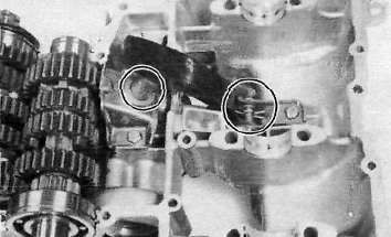
2. Lower crankcase a. Install the shift cam and secure it with the guide pin. Install the stopper plate and bolt and tighten securely.
b. Install the neutral switch.
c. Install the shift forks and guide bar. Each shift fork is identified by a number cast on its side. All the numbers should face the left side and numbered 1, 2 and 3 from left.
d. Install the shift bar stopper securing screw and bolt.
e. Install the transmission assembly into the crankcase, Next, install the HY-VO chain tensioner and chain guide.
CAUTION:
When installing the crankcase, make sure the HY-VO chain tensioner is set in place with its plunger in the proper position; otherwise, a dislodged plunger will result in damage to various part after crankcase installation.
Crankcase Assembly
Crankcase AssemblyCrankcase assembly
a. Apply Yamaha bond # 4 sealant or equivalent to the crankcase mating surface. Be very careful not to allow any sealant to come in contact with the oil gallerly "O-ring" and crankshaft bearings. It is extremely important, however, that sealant be applied around the case stud holes. Apply sealant to within 2~3 mm (0.08 - 0.12 in) of the bearings.
CAUTION:
Failure to apply sealant here will result in reduced oil pressure and possible crank seizure.

1. 2-~ 3 mm (0.08 — 0.12 in) Do not apply sealant.
b. The crankcases are assembled by placing the upper case half on the bench and lowering the lower case onto it.
NOTE:
Be sure that shift fork No. 2 engages the groove in the 2nd pinion gear on the main axle.
CAUTION:
Before installing and torquing the crankcase bolts, check to make sure the transmission is functioning properly by shifting it by hand with the shift cam.

c. Start installation of the crankcase bolts with the center crankshaft area bolts. Place the two bolts without washers in the oil filter area.
d. The crankcase bolts should be torqued in proper sequence. Refer to the tightening sequence in the illustration.
e. Install the right-front crankcase cover. 4. Oil pump and strainer cover a. Install the relief valve, strainer housing and strainer screen.


Tightening torque: 1.0m-kg(7.2ft-lb)
b. Install the strainer cover and torque the bolts to the specification.
Tightening torque: 1.0m-kg(7.2ft-lb)

1. Wire clamps
c. Install the shift lever assembly with the positioning spring is properly located on the stopper pin.

d. Install the oil pump assembly and oil pump securing screws.

e. Install the oil pump driven sprocket.

Pistons and Cylinders
Pistons and Cylindersa. Install the pistons on the rods. The arrow on the piston must point to the front of the engine.
NOTE:
Before installing the piston pin clips, cover the crankcase with a clean rag so you will not accidentally drop the circlip into the crankcase. Always install new piston pin circlips.

b. Install the rear chain guide on its pivot. Tighten the holding bolt until it stops and then loosen 1/4 turn and then tighten the lock nut.

1. Holding bolt 2. Rear chain guide
c. Install the new cylinder base gasket and dowel pins. Install the new "O-rings" to the right side dowel pins.

d. Set the crankshaft so that the all pistons are equal height and align the piston rings as shown.

CAUTION;
Make sure the ends of the oil ring expanders are not overlapped.
NOTE:
Manufacturer's marks or numbers stamped on the rings are on the top side of the rings. Coat the pistons and rings well with oil.
e. Install the piston ring compressors (special tool) and piston bases (special tool). Four piston bases are required.

1. Piston bases 2. Piston ring compressors
f. Tie the cam chain with a piece of mechanic's wire and feed it through the chain opening. Carefully lower the cylinder onto the pistons. Remove the ring compressors and piston bases and repeat this procedure for pistons 1 and 4.

g. Install the cylinder securing nut (front side) and tighten it to the specification.
Tightening torque: 2.0 m-kg (14.5 ft-lb)

h. Set the dial guage on the No. 1 piston head center as shown to find the No. 1 piston top dead center and check whether the "T" mark on the timing plate and stationary pointer are aligned or not, If not, loosen the pointer securing screw and adjust.

AC Generator, Starter Motor and Pickup coil
AC Generator, Starter Motor and Pickup coilGenerator
a. Install the rotor onto the shaft and tighten the bolt using the rotor holding tool (special tool) as shown.

1. Rotor holding tool
Tightening torque: 3.5 m-kg (25.5 ft-lb)
b. Install the stator coil assembly onto the crankcase and align the grooves on the stator core with the bolt holes on the crankcase.

c. Install the A.C.G. cover assembly and tighten the bolts to the specification. Do not forget to install the new gasket.
Tightening torque: 1.0m-kg(7.2ft-lb)

Starter motor
a. Route the A.C.G. lead wires as shown.
b. Install the starter motor and tighten the bolts to the specification.
Tightening torque: 1.0m-kg (7.2fMb)
NOTE:
Be careful the "O-ring" is not damaged when installing the starter motor.
Pick-up coil assembly
a. Install the pick-up coil assembly onto the crankcase.
b. Install the timing plate on the crankshaft and tighten the bolt to the specification.
NOTE:
Note that there is the locating pin on the crankshaft and the corresponding slot in the timing plate which must be aligned to install the timing plate.

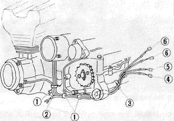
1. Clamp
2. To side stand switch
3. Band
4. Side stand switch lead wire
5. Pick up coil and lead wire
6. A.C Generator lead wire
Clutch
ClutchClutch assembly
a. Install the primary drive gear and collar.
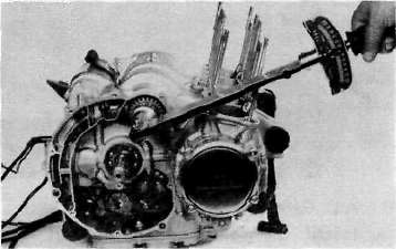
Tightening torque: 5.0 m-kg (36.0 ft-lb)
b- Install the primary driven gear assembly.
c. Install the clutch boss and thrust plate.
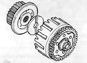
d. Install a new lock washer and nut and tighten the nut to the specified torque. Use the clutch boss holder (special tool).
Tightening torque: 7.0 m-kg (50.5 ft-lb)
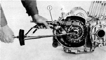
1. Clutch boss holder
e. Bend the lock washer tabs along the nut flats.
f. Install the clutch plates and friction plates alternately on the clutch boss, starting with a friction plate and ending with a friction plate.
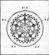
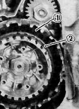
1. Third friction plate 2. Clutch boss spring
g. Install the plate washer, thrust bearing, and clutch pull rod into the clutch pressure plate from inside.
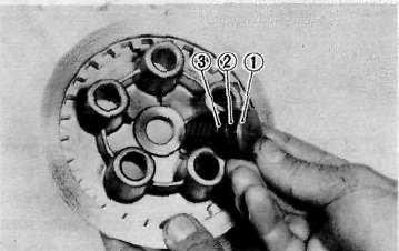
1. Pull rod 2. Thrust bearing 3. Plate washer
h. Install the pressure plate assembly onto the clutch boss.
NOTE:
Pressure plate has a dot on it which must line up with the dot on clutch boss.
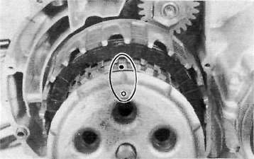
i. Install the clutch springs and screws. Tighten the screws.
Clutch screw torque: 0.8m-kg(5.8ft-lb)
j. Set the gear of the clutch pull rod on the pressure plate facing approximately 90° from horizontal toward the rear; set the clutch lever (if installed) on the right crankcase cover parallel to the gasket surface and install the cover to the crankcase. Do not forget to install two dowel pins.
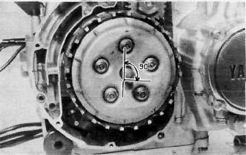
k. If the clutch lever has been removed, install the lever return spring and lever on the shaft after installing the right crankcase cover. In this case make sure that the punch mark on the lever should align with the mark on the crankcase cover when pushing the lever towards the front by hand and then install the circlip.
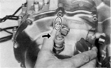
Cylinder head and Camshafts
Cylinder head and Camshaftsa. Install the new cylinder head gasket. Install the dowel pins and "o-rings".

b. Install the cylinder head onto the cylinder. Pull the cam chain through the cylinder head as it is installed. Tie the cam chain so that it does not fall into the crankcase.
c. Place the upper cylinder head nuts and washers in place. Follow the illustration for the proper tightening sequence. Torque all nuts in two stages and final torque the upper nuts to the specification.
Tightening torque: 2.0 m-kg (14.5 ft-lb)
Don't forget the lower nuts on the front and rear of the cylinder head. Torque to the specification.
Tightening torque: 1.0 m-kg (7.2 ft-lb)

1. Copper washers

NOTE
Tighten the nuts in two stages, 1/2 torque value and then full torque value. Also lubricate the bolt threads with the engine oil to achieve proper torque values.
d. Install the front cam chain guide being certain that it is in its holder down below.

1. Lock washer 2. Front cam chain guide
e. Rotate the engine in a counterclockwise direction until the crankcase pointer and "T" mark on the timing plate are aligned.

f. With the cylinder No. 1 and 4 at the top dead center, slip the cam chain over the sprocket.
g. Lubricate at! cam caps and cam bearings surfaces liberally with oil.

h. Place the cam caps in their proper positions. The caps are identified "1-1" through "I-4" for intake and "E-1" through "E-4" for exhaust. Install the bolts only finger tight.

CAUTION:
The cam caps must be tightened evenly or damage to the cylinder head, cam caps and cam will result. The spaces between the caps and cylinder head should be equal.
i. Torque the cam cap bolts in two stages and final torque to specification.
Tightening torque: 1.0 m-kg (7.2 ft-lb)
Cam chain, cam sprockets and chain tensioner.
Cam chain, cam sprockets and chain tensioner.a. Rotate each cam shaft until the dot on the cam is aligned with the arrow on the center cam cap.
CAUTION:
Use extreme caution when rotating the cams. Two possible dangers exist. First, the wrench may contact the head and fracture it. Or second, a valve may become bent if the cam is turned the wrong way.
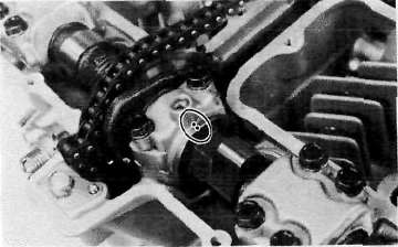
b. Carefully lift the cam chain from the exhaust cam sprocket and pull upward to remove any slack in the chain between the crankshaft and the exhaust cam sprocket. With all slack removed, place the chain back on the cam sprocket.
c. Grip each sprocket simultaneously and place them on the camshaft shoulders while continuing to keep tension on the chain from the crankshaft to the exhaust sprocket.
CAUTION:
Use only the special hardened shouldered bolts to install the cam chain sprockets to the cams.
Make sure the rollers of the cam chain are centered on both chain guides.
d. Rotate the sprockets slightly to align the bolt holes and insert one special bolt in each sprocket.
NOTE:
Tighten only finger tight at this time.
e. Install the center chain guide.
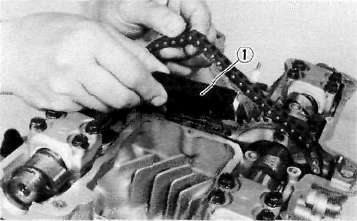
1. Cam chain guide
f. Rotate the crankshaft counterclockwise and align the "C" mark on the timing plate with the timing pointer.
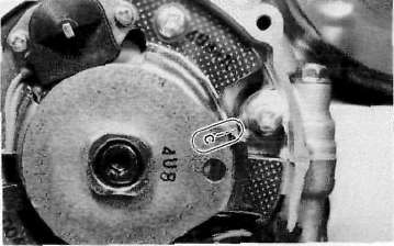
g. Compress the cam chain tensioner and lock in the retracted position.
h. Install the chain tensioner to the engine and torque the bolts to the specification.
Tightening torque: 1.0 m-kg (7.2 ft-lb)
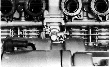
L Release the tensioner holding bolt, an audible click will be heard when the tensioner is released.
j. Torque the holding bolt and the lock nut to the specifications.
Holding bolt torque: 0.6 m-kg (4.3 ft-lb)
Lock nut torque: 0.9 m-kg (6.5 ft-lb)
k. Rotate the crankshaft more than one full revolution and align the "T" mark on the timing plate with the timing pointer. With the crankshaft at the "T" mark, the dots on the cams should be aligned with the raised arrows on the center cam caps. If they are not aligned, disassemble the sprockets and chain tensioner and repeat above procedures.
I. Rotate the crankshaft and install the two remaining shoulder bolts into the cam sprockets. Torque all four sprocket holding bolts to the specification.
CAUTION:
Be sure to attain the specified torque value to avoid the possibility of these bolts coming loose and causing serious damage to the engine.
Tightening torque: 2.0 m-kg (14.5 ft-lb)
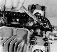
m. Adjust all valves as described in the "PERIODIC INSPECTIONS AND ADJUSTMENTS".
n. Install the cylinder head cover with a new gasket.
o. Install the left crankcase covers. The left crankcase cover (pick-up coil cover) is required a gasket.
Remounting Engine
Remounting EngineRefer to Engine Removal. Reverse the applicable removal steps.
CAUTION:
Always use new bolts in the drive shaft coupling.
2. Install and tighten the engine mounting bolts.
Engine mounting bolt torque:
10 mm nut: 4.2 m-kg (30.5 ft-lb)
10 mm bolt: 4.2 m-kg (30.5 ft-lb)
12 mm nut: 7.0 m-kg (50.5 ft-lb)
3. Fill the oil fitler with approx. 0.3 lit (0.3 qt.) engine oil and install the oil filter.
CAUTION:
The filter must be filled with the specified amount of oil to prime the oil pump of an overhauled engine.
4. Tighten engine oil drain plug, oil filter mounting bolt.
Torque:
Engine oil drain plug: 4.3 m-kg (31.0 ft-lb)
Oil filter mounting bolt: 1.5 m-kg (11.0 ft-lb)
Middle gear drain plug:2.4 m-kg (17.5 ft-lb)
5. Add oil to the engine.
Engine oil: 2.6 lit (2.3 US qt.)
Chapter 4. Carburetion
Chapter 4. CarburetionCARBURETOR
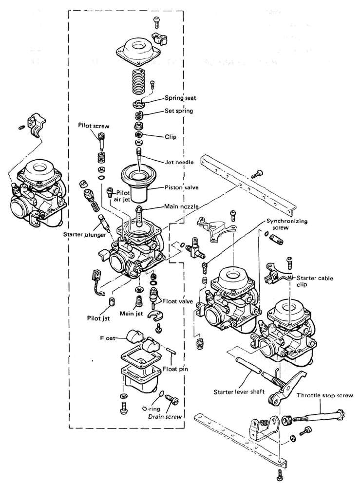
A. Section view

B. Specifications
|
Main jet |
# 112.5 |
|
Jet needle |
4GZ11 |
|
Needle jet |
O-S |
|
Starter jet |
#35 |
|
Fuel level |
2+ 1 mm{0.079±0039in) |
|
Pilot screw |
Preset |
|
Float valve seat |
<J> 2.0 |
|
Engine idle speed |
1,200 r/min |
CAUTION:
The pilot screw settings are adjusted for maximum performance at the factory with the use of specialized equipment. Do not attempt to change these settings. If all other engine systems are functioning correctly, any changes will decrease performance and cause increased exhaust emissions.
Disassembly and reassembly
Disassembly and reassembly
CAUTION:
Separation of the carburetors is not recommended. Usual disassembly for cleaning and inspection does not require separation of the carburetors. The carburetor body support screws are locked with a locking compound such "LOCTITE". If the carburetors are separated, misalignment will result.
1. Loosen the starter lever securing screws and remove the starter lever shaft.

2. Remove the vacuum chamber cover and remove the spring and diaphragm (vacuum piston).
NOTE:
Note that there is the tab on the rubber diaphragm. There is the matching recess in the carburetor body for the diaphragm tab.

3. Remove the pilot air jet.

I. Pilot air jet
4. Remove the screws holding the float chamber cover and remove the cover. The main and pilot jets are located in the float bowl. Remove the jets if necessary.


1. Pilot jet 2. Main jet
5. Pull out the float pivot pin. Remove the float assembly. Be careful to not lose the float valve under the float arm. Remove the float valve seat.

1. Float valve seat
6. Reasemble in reverse order. Pay close attention to the installation of the vacuum piston diaphragm and the location of each jet.
7. If the carburetors should be separated, care must be taken so that they are put together in place according to the following procedures:
a. Place the carburetors on a surface plate and install the lower support plate. Apply a thread locking compound such as "LOCTITE" and tighten the screws securely while holding the carburetor body.

1. Lower support plate 2. Surface plate
NOTE:
When reassembling, the surface plate should be used for the proper carburetor alignment.
b. Install the upper support plate. Apply a thread locking compound such as "LOCTITE" to the support screw threads and tighten the screws securely.
Inspection and Adjustment
Inspection and Adjustment1. Examine the carburetor body and fuel passages. If contaminated, wash the carburetor in a petroleum-based solvent. Do not use caustic carburetor cleaning solutions. Blow out all passages and jets with compressed air.
2. Examine the condition of the floats. If the floats are damaged, they should be replaced.
3. Inspect the float needle valve and seat for wear or contamination. Replace these components as a set.

4. Inspect the vacuum piston and rubber diaphragm. If the piston is scratched or the diaphragm is torn, the assembly must be replaced.

1. Vacuum piston 3. Set spring
2. Needle Jet
5. Inspect the starter plunger for damage, If damaged, replace.

E. Adjustment
Fuel level
NOTE:
Before checking the fuel level, note the following:
1. Place the motorcycle on a level surface.
2. Adjust the motorcycle position by placing a suitable stand or a garage jack under the engine so that the carburetor is positioned vertically.
1. Connect the level gauge adapter (special tool) to the carburetor drain hole.
2. Connect the level gauge (special tool) or a vinyl pipe of 6 mm (0.24 in) in inside dia. to the level gauge adapter.
3. Set the gauge as shown and loosen the drain screw.

1. Level gauge adapter 2. Level gauge 3. Drain screw
4. Start the engine and stop it after a few minutes of running. This procedure is necessary to obtain the correct fuel level. Make sure the fuel petcock is "ON" or "RES" position.
5. Note the fuel level and bring the gauge to the other end of the carburetor line and repeat step 4 above. Note the fuel level again and compare it with the previous gauge reading. They should be equal. If not, place a suitable size of wooden piece or the life under the center stand and adjust.

6. Check the fuel level one by one. The level should be in the specified range.
Fuel level: 2 ± 1 mm (0.079 ± 0.039 in) below from the carburetor mixing chamber body edge.

7. If the fuel level is incorrect, remove the carburetor assembly from the motorcycle and check the fuel valve(s) and float assembly(s) for damage.
8. If no damage is found, correct the fuel level by slightly bending the float arm tang. Recheck the fuel level.

1. Float arm tang
Air Cleaner and Crankcase Ventilation System
Air Cleaner and Crankcase Ventilation System


Chapter 5. Chassis
Chapter 5. ChassisCable and Fittings
Cable and FittingsA. Cable maintenance
NOTE:
See Maintenance and Lubrication intervals charts. Cable maintenance is primarily concerned with preventing deterioration through rust and weathering and providing proper lubrication to allow the cable to move freely within its housing. Cable removal is straight forward and uncomplicated. Removal will not be discussed within this section.
A. Checking for excessively 1.1/2 tooth
worn chain 2. Pull

WARNING:
Cable routing is very important. For details of cable routing, see the cable routing diagrams at the end of this manual. Improperly routed or adjusted cables may make the motorcycle unsafe for operation.
1. Remove the cable.
2. Check for free movement of cable within its housing. If movement is obstructed, check for fraying or kinking of the cable strands. If damage is evident, replace the cable assembly.
3. To lubricate the cable, hold it in a vertical position. Apply lubricant to the uppermost end of cable. Leave it in the vertical position until lubricant appears at the bottom. Allow any excess to drain and reinstall the cable.
NOTE:
Choice of lubricant depends upon conditions and preferences. However, a semi-drying chain and cable lubricant will perform adequately under most conditions.
B. Throttle maintenance
1. Remove the Phillips head screws from throttle housing assembly and separate the two halves of housing.
2. Disconnect the cable end from the throttle grip assembly and remove the grip assembly.
3. Wash all parts in a mild solvent and check all contact surfaces for burrs or other damage. (Also clean and inspect right-hand end of the handlebar.)
4. Lubricate all contact surfaces with a light coat of lithium soap base grease and reassemble.
NOTE:
Tighten the housing screws evenly to maintain an even gap between the two halves.
5. Check for smooth throttle operation and quick spring return when released and make certain that the housing does not rotate on the handlebar.
Front Wheel
Front WheelA. Removal
1. Place the motorcycle on the center stand.
2. Remove the cotter pin and wheel axle nut.
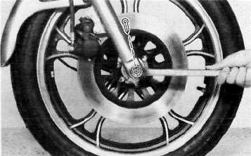
3. Loosen the pinch bolt securing the axle.

1. Pinch bolt
4. Remove the axle shaft and the front wheel. In this case, make sure the motorcycle is properly supported.
NOTE:
Do not depress the brake lever when the wheel is off the motorcycle as the brake pads will be forced to shut.

B. Front axle inspection
Remove any corrosion from the axle with fine emery cloth. Place the axle on a surface plate and check for bends. If bent, replace axle. Do not attempt to straighten a bent axle.
C. Front wheel inspection
This motorcycle is equipped with aluminum wheels designed to be compatible with either tube or tubeless tires.
Tubeless tires are installed as standard equipment.
WARNING:
Do not attempt to use tubeless tires on a wheel designed for use only with tube-type tires. Tire failure and personal injury may results from sudden deflation.
Tube-type Wheel > Tube-type Tires Only
Tubeless-type Wheel > Tube-type or Tubeless tires
WARNING:
When using tube-type tires, be sure to install the proper tube also.


Tubeless Tire

Tube-type Tire

Refer to "Tubeless Tire and Aluminum Wheel Manual" for the proper tubeless and aluminum wheel servicing.
1. Check for cracks, bends or warpage of wheels. If a wheel is deformed or cracked, it must be replaced.
2. Check wheel run-out. If the deflection exceeds the tolerance below, check the wheel bearings or replace the wheel as required.
Rim-run-out limits:
Vertical - 2 mm (0.079 in) Lateral - 2 mm (0.079 in)
3. Check wheel balance. Rotate the wheel lightly several times and observe resting position. If the wheel is not statically balanced, it will come to rest at the same position each time. Install an appropriate balance weight at lightest position (at top).
NOTE:
The wheel should be balanced with the brake disc installed.
4. After installing a tire, ride conservatively to allow the tire to seat itself on the rim properly. Failure to allow proper seating may cause tire failure resulting in damage to the motorcycle and injury to the rider.
5. After repairing or replacing a tire, check to be sure the valve stem lock nut is securely fastened. If not, torque it as specified.
Tightening torque: 0.15 m-kg (1.1 ft-lb)
D. Replacing wheel bearings
If the bearings allow play in the wheel hub or if wheel does not turn smoothly, replace the bearings as follows:
1. Clean the outside of the wheel hub.
2. Drive the bearing out by pushing the spacer aside and tapping around the perimeter of the bearing inner race with a soft metal drift pin and hammer. The spacer "floats" between the bearings. Both bearings can be removed in this manner.
WARNING:
Eye protection is recommended when using striking tools.
3. To install the wheel bearing, reverse the above sequence. Use a socket that matches the outside race of the bearing as a tool to drive in the bearing.
CAUTION:
Do not strike the center race or balls of the bearing. Contact should be made only with the outer race.
E. Installing front wheel
When installing the front wheel, reverse the removal procedure. Note the following points:
1. Lightly grease the lips of the front wheel oil seals and the gear teeth of speedometer drive and driven gears. Use lightweight lithium soap base grease.
2. Make sure the projecting portion (torque stopper) of the speedometer housing is positioned correctly.

1. Torque stopper
3. Tighten the axle nut and install a new cotter pin.
Axle nut torque: 10.5 m-kg (76.0 ft-lb)
4. Before tightening the pinch bolt, compress the front forks several times to make sure of proper fork operation.
5. Tighten the axle pinch bolt.
Axle pinch bolt torque: 2.0 m-kg (14.5 ft-lb)
Front Brake
Front Brake
CAUTION:
Disc brake components rarely require disassembly. Do not disassemble components unless absolutely necessary. If any hydraulic connection in the system is opened, the entire system should be disassembled, drained, cleaned and then properly filled and bled upon reassembly. Do not use solvents on brake internal components. Solvents will cause seals to swell and distort. Use only clean brake fluid for cleaning. Use care with brake fluid. Brake fluid is injurious to eyes and will damage painted surfaces and plastic parts.
A. Caliper pad replacement
It is not necessary to disassemble the brake caliper and brake hose to replace the brake pads.
1. Remove the front fender and front wheel.
2. Unhook the pad retaining pin clip and remove the clip.
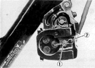
1. Pad retaining pin 2. Clip
3. Pull out the pad retaining pin.

1. Pad retaining pin
4. Remove the pads.
5. Install the new brake pads and shims. Before installing the pads, install the shim on the back plate which faces the caliper piston, as shown. Also replace the following parts if pad replacement is required.
a. Pad spring
b. Shim
c. Pad retaining pin
d. Clip
NOTE:
Replace the pads as a set if either is found to be worn to the wear limit.

1. Shim 2. Disc rotating direction

B. Caliper disassembly

1. Remove the brake hose from the caliper. Allow the caliper assembly to drain into a container.
2. Place the open hose end into the container and pump the old fluid out of the master cylinder.
3. Remove the pad spring, shim, pad retaining pin, clip and pads.
4. Remove the brake caliper holding bolt from the front fork.
5. Remove the dust seal.
6. Carefully force the piston out of the caliper cylinder with compressed air. Never try to pry out the piston.
WARNING:
Cover the piston with a rag. Use care so that piston does not cause injury as it is expelled from the cylinder.
7. Remove the piston seal.
C. Master cylinder disassembly
1. Remove the brake light switch.
2. Remove the brake hose.

3. Remove the brake lever and spring.
4. Remove the master cylinder from the handlebar. Remove the cap and drain the remaining fluid.
5. Remove the master cylinder dust boot.
6. Remove the snap ring.

7. Remove the master cylinder cup assembly. Note that the cylinder cups are installed with the larger diameter (lips) inserted first.
D. Brake inspection and repair
Recommended Brake Component Replacement Schedule:
Brake pads; As required
Piston seal, dust seal; Every two years
Brake hoses; Every four years
Brake fluid; Replace only when brakes are disassembled
1. Replace the caliper piston if it is scratched.
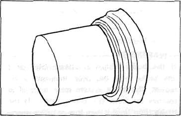
2. Replace any brake pad worn beyond limits. Always replace the brake pads as a set.
See Caliper Pad Replacement procedure for a listing of the parts to be replaced when pads are replaced.
Wear limit: 4.0 mm (0.16 in)
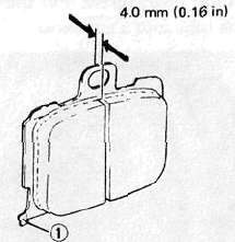
1. Wear indicator
3. Replace piston and dust seals if damaged. Replace seals every two years.
4. Inspect master cylinder body. Replace if scratched. Clean all passages with new brake fluid.
5. Inspect the brake hoses. Replace every four years or immediately if cracked, frayed, or damaged.
6. Check for wear and deflection of disc.

Maximum deflection: 0.15 mm (0.006 in)
Minimum disc thickness: 4.5 mm (0.18 in)
If disc is worn beyond minimum thickness or deflection exceeds specified amount, replace disc.
E. Brake reassembly
1. Caliper reassembly
All internal parts should be cleaned in new brake fluid only. Internal parts should be lubricated with brake fluid when installed. Replace the following parts whenever a caliper is disassembled.
Bleed screw and rubber cap
Piston seal
Dust seal

a. Install the piston seal and piston.
b. Install the pads.
2. Install the caliper assembly on the front fork.

Caliper holding bolt torque: 4.5 m-kg (32.5 ft-lb)
4. Attach the brake hoses.
Brake hose torque: 2.6 m-kg (19.0 ft-lb)
5. Brake disc assembly
If brake disc has been removed from hub or is loose, tighten bolts. Use new locking washers and bend over locking
tabs after bolts are tightened.
Disc bolt torque: 2.0 m-kg (14.5 ft-lb)
6. Master cylinder reasembly
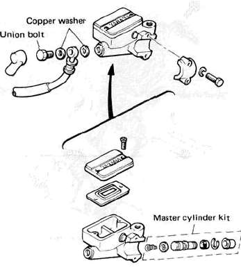
Reassemble master cylinder as shown in illustration.
Brake hose torque: (all brake union bolts) 2.6 m-kg (19.0 ft-lb)
7. Air bleeding
WARNING:
If the brake system is disassembled or if any brake hose has been loosened or removed, the brake system must be bled to remove air from the brake fluid. If the brake fluid level is very low or brake operation is incorrect, bleed the brake system. Failure to bleed the brake system properly can result in a dangerous loss of braking performance.
a. Add proper brake fluid to the reservoir. Install the diaphragm, being careful not to spill or overflow the reservoir.
b. Connect the clear plastic tube of 4.5 mm (3/16 in) inside diameter tightly to the caliper bleed screw. Put the other end of the tube into a container.

c. Slowly apply the brake lever several times. Pull in the lever. Hold the lever in "on" position. Loosen the bleed screw. Allow the lever to travel slowly toward its limit. When the limit is reached, tighten bleed screw. Then release the lever.
d. Repeat step "c" procedure until all air bubbles are removed from system.
NOTE:
If bleeding is difficult, it may be necessary to let the brake fluid system stabilize for a few hours. Repeat the bleeding procedure when the tiny bubbles in the system settle out.
Front Forks
Front Forks

A. Removal and disassembly
WARNING:
Securely support the motorcycle so there is no danger of it falling over.
1. Remove the cowling assembly.
2. Disconnect the speedometer cable. Disconnect the brake caliper and remove the front wheel. Place a wooden wedge or other object into the caliper assembly to keep the brake pads from falling out. Remove the front fender.
3. Remove the rubber cap from the top of each fork.
4. The spring seat and fork spring are retained by a stopper ring (spring wire circlip). It is necessary to depress the spring seat and fork spring to remove the stopper ring. Remove the stopper ring by carefully prying out one end with a small screwdriver.
5. Place an open container under each drain hole. Remove the drain screw from each outer tube.
WARNING:
Do not allow oil to contact the disc brake components. If any oil should contact the brake components it must be removed before the motorcycle is operated. Oil will cause diminished braking capacity and will damage the rubber components of the brake assembly.
5. Loosen the pinch bolts on the steering stem and the pinch bolts on the handle crown, remove the fork.
6. Remove the Allen from the bottom of the fork assembly while holding the inner tube with the front fork cylinder comp. holder (special tool). Pull the inner tube out of the outer tube.

7. To remove the fork seal. Pry out the dust seal and remove the spring clip over the oil seal. Pry out the oil seal, being very careful to not damage the fork tube surfaces.

1. Dust seal
B. Inspection
1. Examine fork inner tube for scratches and straightness. If the tube is scratched severely or bent, it should be replaced.
WARNING:
Do not attempt to straighten a fork tube, since this may weaken the part dangerously.
2. Check the seal outer seat. If leakage is from this area, replace the seal. If this does not cure the leakage, replace the outer tube.
3. Check the outer tube for dents. If any dent causes the inner tube to "hang up" during operation, the outer tube should be replaced.
4. Check the free length of the springs.
Fork spring free length: 508 mm (20.00 in)
5. Check the "O-ring" on the spring seat. If damaged, replace the "O-ring",
C. Assembly
1. Make sure all components are clean before assembly. Always install a new fork seal. Do not re-use seal.
2. Apply oil to the fork seal and install the seal by pressing in with a large socket. Install the retaining clip and dust seal.
3. Install the inner tube into the outer tube. Install and tighten alien bolt and washer. The assembly procedure is the reverse of the disassembly procedure.
NOTE:
When installing the fork springs, the greater pitch should be at the bottom. The main fork spring has a small coil diameter at the bottom.
4. Reinstall the spring seat.
CAUTION:
Always use a new stopper ring (spring wire circlip).

1. Top 2. Small pitch
Steering Head
Steering HeadSTEERING HEAD

A. Adjustment
Refer to "D. Reassembly" for steering head adjustment procedure.
B. Removal
1. Remove the cowling assembly, meters, horn, front wheel, front forks, handlebar cover and handlebars.
2. Remove the front brake pipe junction.

3. Remove the stem bolt and steering crown.

4. Support the steering stem (under bracket) and remove the fitting nut (ring nut).
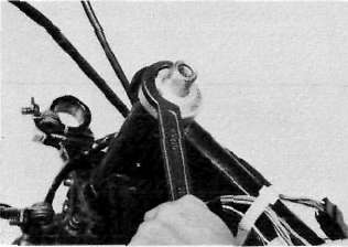
5. Remove the top bearing race and all of the bearing balls from the upper bearing.
Ball quantity (upper and lower): 38 pcs.

C. Inspection
1. Wash the bearings in solvent.
2. Inspect the bearings for pitting or other damage. Replace the bearings if pitted or damaged. Replace the races when bearing balls are replaced.
3. Clean and inspect the bearing races. Spin the bearings by hand. If the bearings are not smooth in their operation in the races, replace bearing balls and races.

I. Bearing race
D. Reassembly
1. Grease the bearings and races with wheel bearing grease.

2. Install the steering stem (under bracket), bearing balls, and races.
3. Install the bottom fitting nut. Tighten it to approximately 2.5 m-kg (18 ft-lb) and loosen it approximately 1/4 turn.
4. Tighten the fitting nut securely with the ring nut wrench.
5. Continue reassembly in the reverse of disassembly order.
6. When assembly is complete, check the steering stem by turning it from lock to lock. If there is any binding or looseness, readjust the steering stem tightness.
Steering stem bolt torque: 5.4 m-kg (30.0 ft-lb)
Rear Wheel
Rear WheelA. Removal
1. Place the motorcycle on the center stand.
2. Remove the tension bar and the brake rod from the brake shoe plate. The tension bar can be removed by removing the cotter pin and nut from the tension bar bolt. The brake rod can be removed by removing the adjuster.

1. Adjuster 3. Tension bar
2. Brake rod
3. Remove the axle nut cotter pin and loosen the axle nut.

4. Loosen the adjusting bolt and let the chain puller down as in the photo.

1. Adjusting bolt 2. Chain puller 3. Pinch bolt 4. Rear arm end
5. Remove the pinch bolt and chain puller attachment.
6. Push the rear wheel forward and remove the drive chain.
7. The rear wheel can be removed by pulling the wheel axle, backward.

B. Checking brake shoe wear
1. Measure the outside diameter at the brake shoes with slide calipers.
Front brake shoe diameter: 160 mm (6.30 in)
Replacement limit: 156 mm min. (6.14 in)

a. Measuring points
2. Remove any glazed areas from the brake shoes using coarse sand paper.
C. Brake drum
Oil or scratches on the inner surface or the brake drum will impair braking performance or result in abnormal noises.Remove oil by wiping with a rag soaked in lacquer thinner or solvent. Remove scratches by lightly and evenly polishing with emery cloth.
D. Brake shoe plate
Remove the camshaft and grease. If the cam face is worn, replace.
NOTE
Before removing the cam lever, put a match mark on the cam lever and camshaft to indicate their positions for easy assembly.
E. Rear axle inspection
(See Front wheel axle inspection procedure.)
F. Replacing wheel bearings
Rear wheel bearing replacement is similar to the procedure for the front wheel.
G. Rear wheel inspection
(See Front wheel. Inspection procedures)
H. Installing rear wheel
1. Lightly grease lips of rear wheel oil seals.
2. After installing the rear wheel, make sure the axle nut is properly torqued and a new cotter pin is installed.
CAUTION:
Always use a new cotter pin on the axle nut.
Tightening torque: Axle nut: 10.5 m-kg (76.0 ft-lb)
3. Adjust the drive chain.
4. Adjust the rear brake.
Rear Shock, Drive chain and Sprocket
Rear Shock, Drive chain and SprocketA. Removal
1. Remove one (1) rear shock absorber at at time, inspect and reinstall before removing the other.
B. Inspection
1. Check the rod. If it is bent or damaged, replace the shock absorber.
2. Check for oil leakage. If oil leakage is evident, replace the shock absorber.
3. Operate shock absorber rod to check damping. There should be no noticeable damping as the shock extends.
4. Install the shock absorber on the motorcycle.
Tightening torque:
3.0 m-kg (21.5 ft-lb)
DRIVE CHAIN AND SPROCKETS
NOTE:
Please refer to General maintenance and Lubrication charts for additional information.
A. Drive sprocket
With the left crankcase cover removed proceed as follows:
1. Remove the sprocket securing bolts. Remove the holder plate and drive sprocket.
2. Check sprocket wear. Replace if wear decreases tooth width as shown.
3. Replace if tooth wear shows a pattern such as that in the illustration, or as precaution and common sense dictate.
4. Tighten the securing bolts.
Drive sprocket securing bolt torque:
1.0 m-kg (7.2 ft-lb)

1,1/4 tooth 2, Correct 3. Roller 4. Sprocket

1. Slip off 2. Bent teeth
B. Driven sprocket
With the rear wheel removed, proceed as
follows:
1. Using a blunt chisel, flatten the securing nuts lock washer tabs.
Remove the securing nuts. Remove the lock washers and sprocket.
2. Check the sprocket wear using procedures for the drive sprocket.
3. Check the sprocket to see that it runs true. If bent, replace.
4. During reassembly, make sure that sprocket and sprocket seat are clean. Tighten the securing nuts in a crisscross pattern.
Bend the tabs of the lock washers fully against the securing nut flats.
Driven sprocket securing nut torque: 6.2 m-kg (45.0 ft-lb)

C. Chain inspection
1. With the chain installed on the motorcycle, excessive wear may be roughly determined by attempting to pull the chain away from the rear sprocket. If the chain will lift away more than one-half the length of the sprocket teeth, remove and inspect.
If any portion of the chain shows signs of damage, or if either sprocket shows signs of excessive wear, remove the inspect.
2. Check the chain for stiffness. Hold as illustrated. If stiff, soak in solvent solution, clean with wire brush, dry with high pressure air. Oil chain thoroughly and attempt to work out kinks. If still stiff, replace chain.
3. Check the side plate for damage. Check to see if excessive play exists in pins and rollers. Check for damaged rollers. Replace as required.

D. Chain maintenance
The chain should be lubricated according to the recommendations given in the General Maintenance/Lubrication charts, or more often if possible. (Preferably after every use.)
1. Wipe off dirt with shop rag. If accumulation is severe, use wire brush, than rag.
2. Apply lubricant between roller and side plates on both inside and outside of chain. Don't skip a portion as this will cause uneven wear. Apply thoroughly. Wipe off excess.
Recommended lubricant:
Yamaha Chain and Cable Lube or SAE 10W/30 motor oil.
3. Periodically, remove the chain. Wipe and/or brush excess dirt off. Blow off with high pressure air.
4. Soap chain in solvent, brushing off remaining dirt. Dry with high pressure air. Lubricate thoroughly to make sure lubricant penetrates. Wipe off excess. Reinstall.
Swing Arm
Swing ArmSWING ARM

A. Inspection
1, Free play inspection
Remove the rear wheel and both shock absorbers. Grasp the swing arm and try to move it from side to side as shown.
Swing arm free play: 1.0 mm (0.04 in)
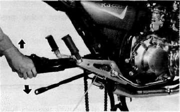
2. If the free play is excessive, remove the swing arm and replace the swing arm bushes.
B. Removal
1. Remove the nut on swing arm pivot shaft and tap out the shaft with a long aluminum or brass rod.
NOTE:
Carefully remove the arm while noting the location of bushes and shims. They must be reinstalled in the same positions.
2. Tap out old bushes from each side of the pivot using the long rod.
3. Install the new bushes using a press.
NOTE:
Do not hammer in the bushes when installing; it may result in breakage to the bushes.
4. For reinstallation, reverse the removal procedure.
Pivot shaft tightening torque: 9.0 m-kg (65.0 ft-ib)
C. Lubrication
1. This model is equipped with the oilless bushes, but it is recommended to apply grease on the bushes lightly.
Recommended lubricant: Lithium soap base grease
2. Wipe off excess grease.
Chapter 6. Electrical
Chapter 6. Electrical
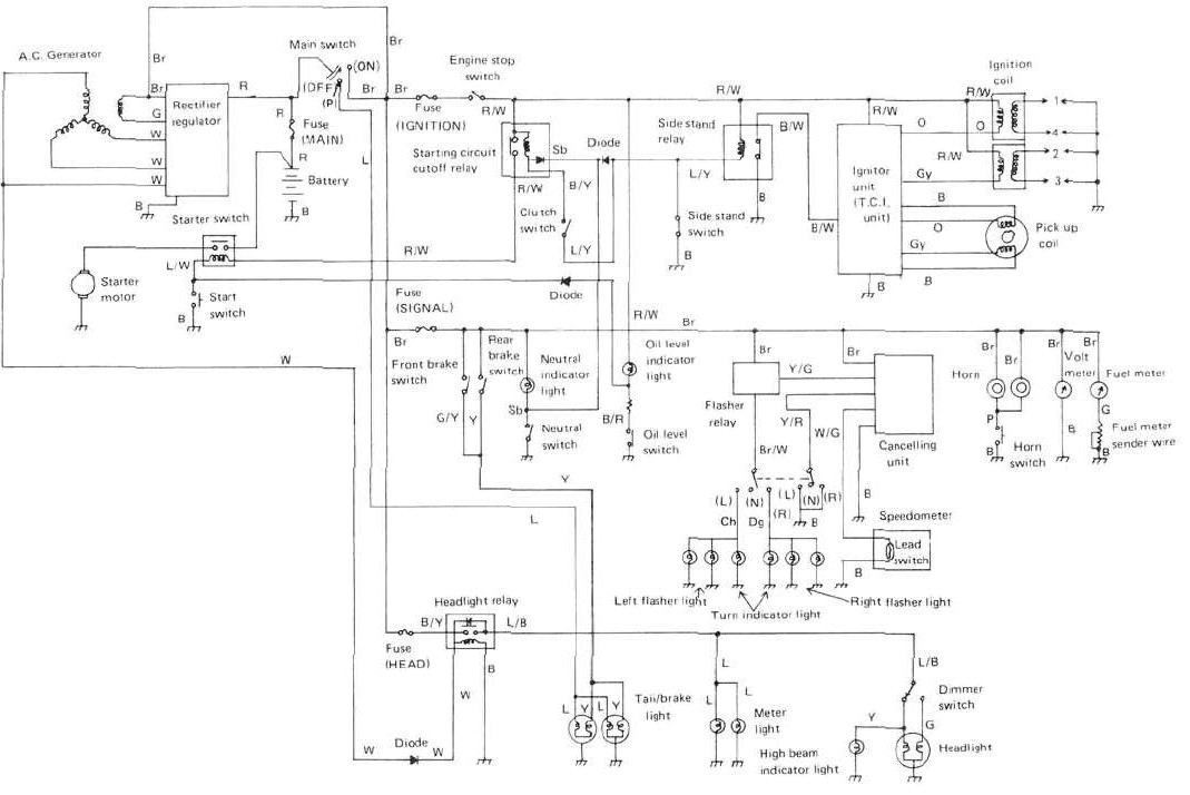
Charging System
Charging SystemCHARGING SYSTEM

B. A.C. generator
1. Checking method.
a. Connect D.C. voltmeter to the battery terminals.
b. Start engine.
c. Accelerate engine to approximately 2,000 r/min or more and check generated voltage.
Generated voltage: 14.5 ± 0.3V

d. If the indicated voltage cannot be reached, then perform the tests in step 2.
CAUTION:
Never disconnect wires from the battery while the generator is in operation. If the battery is disconnected, the voltage across the generator terminals will increase, damaging the semiconductors.
2. Resistance test of field coil and stator coil.
Check the resistance between terminals. If resistance is out of specification, coil is broken. Check the coil connections. If the coil connections are good, then the coil is broken inside and it should be replaced.
Field coil resistance: (Green-Brown) 4.5S2 ± 10%at20°C (68°F)
Stator coil resistance: (White-White) 0.5n ± 10% at20°C(68°F)
Field coil

Stator coil

C. Voltage regulator
The IC Voltage Regulator is a small and, normally, very reliable component. Due to its construction, it is lightweight and free from the wear and misadjustment associated with mechanical voltage regulators. If the follow-
ing inspection reveals that the regulator is faulty, it cannot be adjusted and must be replaced.
1. Checking IC Voltage Regulator
a. Open the seat.
b. Remove the right side cover.
c. Measure the specific gravity of the battery fluid. If it is less than 1.260, remove the battery and recharge until it is more than 1.260. (See page 6-17 for charging procedures)
d. Check the battery terminals and couplers for looseness.
e. Connect two Yamaha pocket testers to the regulator coupler as illustrated.

CAUTION:
Be careful not to let the tester leads short circuit when connecting them to the regulator snap connector leads.
f. Turn the main switch on. Make sure that V2 is less than 1.8V.
NOTE:
Do not turn on lights or signals.
g. Make sure that V2 gradually increases up to 9 ~ 11V when the engine is started and its revolutions go up.

h. Make sure that V1 maintains the level of 14.2 - 14.8V even when engine revolutions increase.
i. If these levels are not maintained, the regulator is defective and must be replaced.
2. Checking the silicon rectifier
a. Check the silicon rectifier as specified using the Yamaha pocket tester.
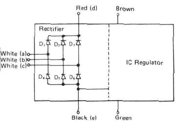
|
Checking element |
Pocket tester connecting point |
Good |
Replace (element shorted) |
Replace (element opened) |
|
|
(red) |
(-1 (black) |
||||
|
D1 |
d |
a |
O |
O |
X |
|
a |
d |
X |
O |
X |
|
|
D2 |
d |
b |
o |
0 |
X |
|
b |
d |
X |
0 |
X |
|
|
D3 |
d |
c |
o |
o |
X |
|
c |
d |
X |
o |
X |
|
|
D4 |
a |
e |
O |
o |
X |
|
e |
a |
X |
o |
X |
|
|
D5 |
b |
e |
0 |
0 |
x |
|
e |
b |
X |
0 |
X |
|
|
D6 |
c |
e |
o |
o |
X |
|
e |
c |
X |
o |
X |
|
O : Continuity
x : Discontinuity (∞)
b. Even if only one of the elements broken, replace the entire assembly.
CAUTION:
The silicon rectifier can be damaged if subjected to overcharging. Special care should be taken to avoid a short circuit and/or incorrect connection of the positive and negative leads at the battery. Never connect the rectifier directly to the battery to make a continuity check.
Ignition System
Ignition SystemIGNITION SYSTEM

B. Description
This model is equipped with a battery operated, fully transistorized breakerless ignition system. By using magnetic pick-up coils and need for contact breaker points is eliminated. This adds to the dependability of the system by eliminating frequent cleaning and adjustment of points and ignition timing. This T.C.I. (Transistor Control Ignition) unit in corporates an automatic advance circuit controlled by signals generated by the pick-up coil. This adds to the dependability of the system by eliminating the mechanical advancer. This T.C.I, system consists of two main units; a pick-up unit and ignitor unit.
C. Operation
The T.C.I, functions on the same principle as a conventional P.C. ignition system with the exception of using magnetic pick-up coils and a transistor control box (T.C.I.) in place of contact breaker points.
1. Pick-up unit

I, Pick-up coils
This unit consists of two pick-up coils and a magneto mounted on the crank-case (L.H.) When the reluctor (timing plate) projection passes the pick-up coil, the two signals are generated at the pickup coil and transmitted to the ignitor unit as a signal. The full ignition advance is determined by the width of the reluctor (timing plate) projection.
2. Ignitor unit

1. Ignitor unit (T.D.I, unit)
This unit has such functions of wave form, duty control, switching, electrical ignition advance, and etc. The ignition timing is advanced electrically using two signals from the pick-up coil. The duty control circuit is provided to control the on time period of the primary ignition current to reduce the electrical consumption. This unit also incorporates a protective circuit for the ignition coil. If the ignition switch is turned on and the crankshaft is not turned, the protective circuit stops current flow to the primary coil within a few seconds. When the crankshaft is turned over, the current is turned on again by the signals generated by the pick-up coils.
CAUTION:
Do not run the engine without any spark plug cap(s) in place. Due to the high secondary voltage, it is possible to damage the internal insulation of the secondary coil.
D. Troubleshooting/ inspection
1. The entire ignition system can be checked for misfire and weak spark using the Electro Tester. If the ignition system will fire across a sufficient gap, the entire ignition system can be considered good. If not, proceed with individual component tests until the problem is found.
a. Warm up engine thoroughly so that all electrical components are at operating temperature.
b. Stop the engine and connect the tester as shown.

c. Start the engine and increase the spark gap until misfire occurs. (Test at various r/min between idle and red line.)
minimum spark gap: 6 mm (0.24 in)
CAUTION:
Do not run engine in neutral above 6,000 r/min for more than 1 or 2 seconds.
2. If the ignition system should become inoperative, the following troubleshooting aids will be useful.
|
Check entire ignition for connections |
|
Correct |
|
|
||
|
Check battery for voltage and specific gravity |
|
Recharge battery |
|
|
||
|
Check fuse and fuse connections |
|
Correct connection or replace fuse |
|
|

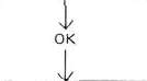


|
Check resistance of ignition coil (primary and secondary) Primary: 2.5 Ω ± 10%at20°C (68°F) Secondary: 11KΩ± 20%at20°C(68°F) |
|
Replace ignition Coil |
|
|
||
|
Check pick-up coils for resistance Pick-up coil: 650 Ω ± 20% at 20°C (68°F) |
|
Replace pick-up Coil |
|
|
||
|
TCI unit is faulty, replace unit |


3. Ignition coil
a. Coil spark gap test
1) Remove the fuel tank and disconnect the ignition coil from wire harness and spark plugs.
2) Connect the Electro Tester as shown.

3) Connect fully charged battery to tester.
4) Turn on spark gap switch and the increase gap to maximum unless misfire occurs first.
minimum spark gap: 6 mm (0.24 in)
b. Direct current resistance test. Use a pocket tester or equivalent ohmmeter to determine resistance and continuity of primary and secondary coil windings.
Standard value: Primary coil resistance:
2.5Ω t 10%at20°C (68°F) Secondary coil resistance:
11KΩ ± 20%at20°C(68°F)
Primary coil check

Secondary coil check

4. Spark plug
The life of a spark plug and its discoloring vary according to the habits of the rider. At each periodic inspection, replace burned or fouled plugs with new ones of the specified type. It is acutally economical to install new plugs often since it will tend to keep the engine in good condition and prevent excessive fuel consumption.
a. Inspection
1) Inspect and clean the spark plug every 4,000 km (2,500 mi) and replace after initial 13,000 km (8,000 mi).
2) Clean the electrodes of carbon and adjust the electrode gap to the specification.
b. Installation
Be sure to use the proper reach, type and electrode gap plug(s) as a replacement to avoid overhating, fouling or piston damage.
Type:
D8EA (NGK) or X24ES-D (ND) Electrode gap:
0.6 - 0.7 mm (0.024 - 0.028 in) Tightening torque:
2.0m-kg (14.5 ft-lb)
Lighting System
Lighting SystemLIGHTING SYSTEM
B. Lighting tests and checks The battery provides power for operation of the headlight, taillight, and meter lights. If none of the above operates, always check battery voltage before proceeding further. Low battery voltage indicates either a faulty battery, low battery water, or a defective charging system. See page 6-5 "CHARGING SYSTEM" for checks of battery and charging system. Also check fuse condition. Replace any "open" fuses. There are individual fuses for various circuits (see complete Circuit Diagram).
NOTE:
Check the headlight bulb first before performing the following check.
1. Headlight check
NOTE:
When the engine is started, the headlight and meter lights come on automatically and the lights stay on until the main switch is turned to "OFF" even if the engine stalls.
|
HEADLIGHT DOES NOT COME ON WHEN ENGINE IS RUNNING |
||
|
|
|
|
|
Check for voltage on "W" wire to headlight relay |
Check AC generator, diode, or wiring circuit |
|
|
|
||
|
Check for battery voltage (12V) on "R/Y" wire to headlight relay |
|
Check fuse "Head" or wiring circuit |
|
|
||
|
Check for battery voltage (12V) on "L/B" wire from headlight relay |
|
Replace headlight relay |


2. Taillight does not work:
a. Check bulb.
b. Check for 12V on blue wire.
c. Check for ground on black wire to tail/ brake light.
|
HIGH BEAM AND/OR LOW BEAM DO NOT LIGHT |
||
|
|
No voltage |
Dimmer switch defective |
|
Check for battery voltage at dimmer switch terminal |
||
|
|
||
|
Check for battery voltage at headlight high beam or low beam terminal |
No voltage |
Open or poor connection between headlight and dimmer switch terminal |
|
|
2. Taillight does not work: a. Check bulb. b. Check for 12V on blue wire. c. Check for ground on black wire to tai brake light. |
|
|
Poor ground or poor connection of headlight wiring |
||


Signal System
Signal SystemSIGNAL SYSTEM

B. Signal system tests and checks The battery provides power for operation of the horn, brakelight, indicator lights and flasher light. If none of the above operates, always check battery voltage before proceeding further. Low battery voltage indicates either a faulty battery, low battery water, or a defective charging system. See "CHARGING SYSTEM" for checks of battery and charging system. Also check fuse condition. Replace any "open" fuses. There are individual fuses for various circuits (see complete Circuit Diagram).
1. Horn does not work:
a. Check for 12V on brown wire to horn.
b. Check for good grounding of horn {pink wire) when horn button is pressed.
2. Brake light does not work:
a. Check bulb.
b. Check for 12V on yellow wire to brake light.
c. Check for 12V on brown wire to each brake light switch (front brake and rear brake switches).
3. Flasher lights(s) do not work:
a. Check bulb.
b. Right circuit:
1) Check for 12V on dark green wire to light.
2) Check for ground on black wire to light assembly.
c. Left circuit:
1) Check for 12V on dark brown wire to light.
2) Check for ground on black wire to light assembly.
d. Right and left circuits do not work:
1) Check for 12V on brown/white wire to flasher switch on left handlebar.
2) Check for 12V on brown wire to flasher relay.
3) Replace flasher relay.
4) Replace flasher switch.
e. Check flasher self-cancelling system. (Refer to flasher self-cancelling system.)
4. Neutral light does not work:
a. Check bulb.
b. Check for 12V on sky blue wire to neutral switch.
c. Replace neutral switch.
6. Oil level warning light does not work:
a. Connect oil level switch (black/red wire) to ground. If light comes on, check for proper oil level.
b. If oil level is correct, replace oil level switch.
C. Self-cancelling flasher system
1. Description:
The self-cancelling flasher system turns off the turn signal after a period of time or distance involved in turning or changing lanes. Generally, the signal will cancel after either 10 seconds, or 150 meters (490 feet), whichever is greater. At very low speed, the function is determined by distance; at high speed, especially when changing speeds the cancelling determination is a combination of both times and distance.
2. Operation:
The handlebar switch has three positions: L (left), OFF, and R (right). The switch lever will return to the "OFF" position after being pushed to L or R, but the signal will function. By pushing the lever in, the signal may be cancelled manually.
3. Inspection
If the flasher self-cancelling system should become inoperative, proceed as follows:
a. Pull off the 6-pin connector from the flasher cancelling unit, and operate the handlebar switch, if the signal operates normally in L, R, and OFF, the following are in good condition.
1) Flasher unit
2) Bulb
3) Lighting circuit
4) Handlebar switch light circuit
If (1) through (4) are in good condition, the following may be faulty:
1) Flasher cancelling unit.
2) Handlebar switch rear circuit.
3) Speedometer sensor circuit.
b. Pull off the 6-pin connector from the flasher cancelling unit, and connect a tester (ohms x 100 range) across the white/green and the black lead wires on the wire harness side. Turn the speedometer shaft. If the tester needle swing back and forth between 0 and co, the speedometer sensor circuit is in good condition. If not, the sensor to wire harness may be inoperative.
c. Pull the 6-pin connector from the flasher cancelling unit. Check if there is continuity between the yellow/red lead wire on the wire harness side and the chassis.
Flasher switch OFF: co Flasher switch L or R: 0 ohms
If the tester needle does not swing as indicated above, check the handlebar switch circuit and wire harness.
d. If no defect is found with the above three check-ups and the flasher cancelling system is still inoperative, replace the flasher cancelling unit.
e. If the signal flashes only when the handlebar switch lever is turned to L or R and it turns off immediately when the handlebar switch lever returns to center, replace the flasher cancelling unit.
Starting System
Starting SystemELECTRIC STARTING SYSTEM

B. Starter motor
1. Removal (see CHAPTER 3. "ENGINE DISASSEMBLY")
2. Inspection and repair
a. Check the outer surface of the commutator. If its surface is dirty, clean with# 600 grit sand paper.
b. The mica insulation between commutator segments should be 0.4 — 0.8 mm (0.02 "- 0.03 in) below the segment level. If not, scrape to proper limits with appropriately shaped tool. (A hack saw blade can be ground to fit.)
NOTE:
Mica insulation of commutator must be undercut to ensure proper operation of commutator.

c. The starter's armature coil should be check with an ohm meter for insulation break down (shorting to each other or to ground) and for continuity. Reference figure is given below.
Coil resistance:
Armature coil: 0.012H at 20°C (68°F
Continuity check

Insulation check
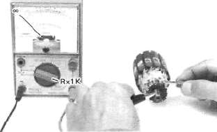
d. Check the front and rear cover bearings for damage. If damaged, the starter assembly must be replaced.
e. Check brush length. Replace brush if at, or near, limits.
Minimum brush length: 5.0 mm (0.20 ia

f. Check brush spring pressure. Compare it with a new spring. Replace the old spring if it is weak.
C. Starter relay switch 1. Inspection
a. Disconnect starter cable at the relay.
b. Connect pocket tester leads to the relay terminals (ohms x 1 scale).
c. Turn ignition to "ON" position, engine stop switch to "RUN" and change lever to "NEUTRAL".
d. Push the starter button. The relay should click once and the scale should read zero if it does not read zero, the relay must be replaced.

1. Baltery lead wire (+)
2. Starter motor lead wire
e. If the relay does not click, check the wires from the starter button and from the battery (red/white, blue/white). Turn the ignition off. Use (ohms x 1) scale on tester. The resistance between these wires should be no more than 3.5 ohms. If there is more resistance, the relay should be replaced.

E. Starting circuit cutoff switch
1. Open the seat and remove the fuel tank.
2. Connect pocket tester leads to the relay terminals (ohms x 1 scale).
3. Check the resistance between terminals. If resistance is out of specification, relay is broken. The relay must be replaced.
Unit: Ω
∞_
|
Pocket tester connecting point |
Black |
||||
|
(+) Red |
|
Blue |
# 1 Red/ While |
Black/ Yellow |
#2 Red/ White |
|
Blue |
|
160 ~240 |
8 ~ 12 |
∞ |
|
|
#1 Red/ White |
∞ |
|
∞ |
||
|
8lack/ Yellow |
∞ |
104 ~156 |
|
||
|
#2 Red/ White |
∞ |
oo |
∞ |
|
|
∞ : Discontinuity

Switches
SwitchesSwitches may be checked for continuity with a pocket tester on the "ohms x 1" position. 1. Main switch
|
Switch Position |
Wire Color |
||
|
R |
Br |
L |
|
|
ON |
|
|
|
|
OFF |
|||
|
LOCK |
|||
|
P (parking) |
|
|
|


2. "ENGINE STOP" switch
|
Switch Position |
Wire Color |
|
|
R/W |
R/W |
|
|
RUN |
|
|
|
OFF |
||


3. "START" switch
|
Button Position |
Wire Color |
|
|
L/W |
Ground |
|
|
PUSH |
|
|
|
OFF |
||


4. "LIGHTS" (Dimmer) switch
|
Switch Position |
Wire Color |
||
|
Y |
L/8 |
G |
|
|
HI |
|
|
|
|
LO |
|
|
|


5. "TURN" switch
|
Switch |
Wire Color |
||||
|
Position |
Ch |
Br/W |
Dg |
Y/R |
Ground |
|
L |
|
|
|
|
|
|
L > N |
|
|
|||
|
N > Push |
|||||
|
R > N |
|
|
|||
|
R |
|
|
|
|
|


6. "HORN" switch
|
Button Position |
Wire Color |
|
|
P |
Ground |
|
|
PUSH |
|
|
|
OFF |
||


Battery and Fuel sender
Battery and Fuel sender1. Checking
If the battery shows the following defects, it should be replaced.
a. The battery voltage will not rise to a specific value or no gassing occurs in any cell even after many hours of charging.
b. Sulfaction of one or more cells is indicated by the plates turning white or an accumulation of material in the bottom of the cell.
c. Specific gravity readings after a long slow change indicate a cell to be lower than any others.
d. Warpage or buckling of plates or insulators is evident.
WARNING:
Battery fluid is poisonous and dangerous, causing severe burns, etc. Contains sulfuric acid. Avoid contact with skin, eyes or clothing.
Antidote:
EXTERNAL-FLUSH with water.
INTERNAL-Drink large quantities of water or milk. Follow with milk of magnesia, beaten egg or vegetable oil. Call physician immediately.
Eyes: Flush with water for 15 minutes and get prompt medical attention. Batteries, produce explosive gases. Keep sparks, flame, cigarettes, etc., away. Ventilate when charging or using in enclosed space. Always shield eyes when working near batteries.
KEEP OUT OF REACH OF CHILDREN.
2. The service life of a battery is usually 2 to 3 years, but lack of care as described below will shorten the life of the battery.
a. Negligence in keeping battery topped off with distilled water.
b. Battery being left discharged.
c. Over-charging with heavy charge.
d. Freezing.
e. Filling with water or sulfuric acid containing impurities.
f. Improper charging voltage or current on new battery.
3. If the motorcycle is not to be used for a long time, remove the battery and have it stored. The following instructions should be observed:
a. Recharge the battery periodically.
b. Store the battery in a cool, dry place.
c. Recharge the battery before reinstalla-tion.
|
Battery |
12N12A-4A |
|
Electrolyte |
Specific gravity l 280 |
|
Initial charging current |
1.2 amp for 10 hours (new battery) |
|
Recharging current |
10 hours {or until specific gravity reaches 1.280) |
|
Refill fluid |
Distilled water (to maximum level line) |
|
Refill period |
Check once per month (or more often if required) |
F. Fuel meter sender unit
1. Open the seat.
2. Connect the pocket tester leads to the sender unit terminals (ohms x 1 scale).
3. Check the resistance between terminals. If resistance is out of specification, unit is broken. The unit must be replaced.
|
Fuel tank condition |
Resistance |
|
FULL |
75-85 Ω |
|
EMPTY |
6~10 Ω |
Chapter 7. Appendices
Chapter 7. AppendicesConsumer Information
Consumer InformationCONSUMER INFORMATION
Notice The information presented represents results obtainable by skilled drivers under controlled road and vehicle conditions, and the information may not be correct under other conditions.
STOPPING DISTANCE
This figure indicates braking performance that can be met or exceeded by the vehicles to which it applies, without locking the wheels, under different conditions of loading and with partial
failures of the braking system.
|
FULL OPERATIONAL SERVICE BRAKE ("Partial failure "information is not applicable and is not included) |
LOAD LIGHT MAXIMUM |
|
|
STOPPING DISTANCE IN FEET FROM 60 MPH |

Carburetor Specifications
Carburetor SpecificationsCarburetion
|
Manufacturer |
MIKUNI |
Fuel level |
2± 1 mm (0.079± 0.039 in) |
|
Model I.D. No. |
5K500 |
Pilot screw |
Preset |
|
Main jet |
# 112.5 |
Air jet. Main |
# 70 |
|
Needle jet |
O-8 |
Air jet. Pilot |
# 165 |
|
Pilot jet |
#35 |
Throttle valve |
# 130 |
|
Starter jet |
# 35 (0.7) |
Float valve seat |
2.0 |
|
Jet needle |
4GN |
Engine idle speed |
1,200 r/m in |
Chassis Specifications
Chassis Specifications"Total weight of accessories, etc. excepting motorcycle.
|
Wheels and tires: Rim run-out: |
2.0 mm (0.079 in) |
|
|
Tire pressure (cold): |
Front |
Rear |
|
Up to 90 kg (198 lb) load* |
1.8 kg/cm2 (26 psi) |
2.0 kg/cm2 (28 psi) |
|
90 kg (198 lb) -192 kg (423 lb) (Maximum load) |
2.0 kg/cm2 (28 psi) |
2.8 kg/cm2 (40 psi) |
|
High speed riding |
2.0 kg/cm2 (28 psi) |
2.3 kg/cm2 (32 psi) |
|
Minimum tire tread depth |
0.8 mm (0.03 in) |
0.8 mm (0.03 in) |
|
Brakes: Recommended fluid |
DOT #3 |
|
|
Front forks: |
150 mm (5.91 in) |
|
|
Rear shock absorber: |
238.5 mm (9.39 in) |
|
Electrical Specifications
Electrical Specifications
|
Ignition timing retarded: |
5° at 1,200 r/min |
|
Ignition timing advance: |
|
|
Spark plug: |
D8EA (NGK) or X24ES-U (ND) |
|
Spark plug cap resistance: |
10KΩ |
|
Pick up coil: Resistance |
650Ωt ± 20%at20°C(68°F) |
|
Ignition coil type:
|
HITACHI CM12-10 2.5Ω ± 10%at20°C(68°F) |
|
|
|
| Starter motor type: Armature coil resistance Brush length: standard minimum Brush spring pressure Armature mica undercut |
MITSUBA SM-8204 12.0 mm (0.472 in) |
| Battery type: | G.S. 12N12A-4A |
|
Charging rate |
1.2 Amps for 10 Hours |
|
Generator type: |
HITACHI LD117-03 |
|
Regulator type: |
I.C. (S8515) |
|
Starter relay switch: |
|
|
Headlight: |
12V.50W/40W 12V,3.4Wx 2 |
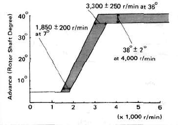
General Specifications
General SpecificationsGeneral Specifications
|
|
XJ550H |
|
Basic color Dimensions: Overall length Overall width Overall height Seat height Wheel base Minimum ground clearance Caster (steering head angle) Trail |
New Yamaha Black or New Ruby Red 2,145 mm (84.4 in) 865 mm (34.1 in) 1,165 mm (45.9 in) 760 mm (29.9 in) 1,420 mm (55.9 in) 160 mm (6.3 in) 28° 114 mm {4.49 in) |
|
Weight: Net |
185 kg (407 lb) |
|
Engine: Type Bore xstroke x cylinders Displacement Compression ratio |
D.O.H.C. air-cooled, gasoline 57.0 x 51.8 mm x 4 (2.244 x 2.039 in x 4) 528 cc (32.22 cu.in) 9.5: 1 |
|
Lubrication: Lubrication system |
Pressure lubricated, |
|
Carburetion: Manufacture Type Rated venturi size |
MIKUNI BS28, constant velocity 28 mm (1.10 in) |
|
Air filter: |
Dry type element |
|
Ignition: Type Spark plug |
Battery ignition (Full transistor ignition) D8EA (NGK) or X24ES-U (ND) |
|
Charging: Type Manufacture, I.D. No. Maximum output Battery type Battery dimensions Regulator/Rectifier Regulating voltage (No. load) |
Three-phase, regulated alternator HITACHI, LD117-03 14V 17A 12N12A-4A 80 x 160 x 134 mm (3.15 x 6.30 x 5.28 in) S8515,1.C. type, full wave 14.2-14.8V |
|
Starting: |
Electric starter |
|
Primary drive: Type Teeth, ratio |
Spur gear 22/21 x 65/28 (2.432) |
|
Clutch: |
Wet, multiple disc |
|
Transmission: Type |
Constant mesh, 6-speed drum shifter |
|
Teeth, ratio |
|
|
Secondary drive: |
|
|
Chassis: Suspension: Tires: Brakes: Fuel tank: Wheels: |
Telescopic fork 150 mm (5.91 in) 3.25H19-4PR,Tubeless Single hydraulic disc
MT1.85 x 19, Cast Aluminum |
Maintenance Specifications
Maintenance Specifications1. Engine
|
Engine oil capacity: Recommended lubricant: |
2,900 cc (3.1 US. qt)
SAE 20W/40SE motor oil SAE 10W/30SE motor oil |
|
Cranking pressure (at sea level): |
8.5 kg/cm2 (121 psi) |
Camshafts:

|
Dimensions |
Standard size |
Wear limit |
|
|
A |
34.80 mm (1.370 in) |
34.65 mm (1.364 in) |
|
|
Intake |
B |
28.0 mm (1.102 in) |
27.85 mm (1.096 in) |
|
C |
6.80 mm (0 268 in) |
- |
|
|
A |
34.80 mm (1.370 in) |
34.65 mm (1.364 in) |
|
|
Exhaust |
B |
28.0 mm (1.102 in) |
27.85 mm (1.096 in) |
|
C |
6.80 mm (0.268 in) |
- |
|
Camshaft bearing surface diameter: 24.967 -24.980 mm (0.9830-0.9835 in)
Camshaft-to cap clearance:
Standard: 0.020- 0.054 mm (0.0008- 0.0021 in)
Maximum: 0.160 mm (0.006 in)
Camshaft runout limit: 0.1 mm (0.004 in)
Valve springs:
Allowable tilt from vertical :1.6 mm (0.063 in)

|
|
Inner Intake/Exhaust |
Outer Intake/Exhaust |
|
Free length |
35.5 mm (1.398 in) |
37.2 mm (1.465 in) |
|
Spring rate |
2.429 kg/mm (136.0 lb/in) |
4.726 kg/mm (264.7 lb/in) |
|
Installed length (valve closed) |
30.5 mm (1.201 in) |
32.0 mm (1.260 in) |
|
Installed pressure (valve closed) |
9.3 kg (20.5 lb) |
18.5 kg (40.8 lb) |
|
Compressed length (valve open) |
IN: 24.0 mm (0.945 in) |
IN: 24.0 mm (0.945 in) |
|
Wire diameter |
2.7 mm (0.106 in) |
3.8 mm (0.150 in) |
|
Number of windings |
7.6 |
6.0 |
|
Winding O.D. |
19.9+0.3 -0 mm (0.783+0.012 -0 in) |
28.3 +0 -0.3 mm (1.114 +0 -0.012 in) |
Valves:
Valve stem run-out maximum 0.03 mm (0.0012 in)
Valve seat width standard/maximum 1.0 mm (0.039 in)/2.0 mm (0.080 in)
INTAKE
|
Clearance (Cold engine) |
0.11~0.15mm (0.004~0.006 in) |
|
"A" head diameter |
30 ± 0.1 mm (1.1811 ±0.0039 in) |
|
"B" face width |
2.3 mm (0.0906 in) |
|
"C" seat width |
1.0± 0.1 mm (0.0394 ± 0.0039 in) |
|
"D" margin thickness (minimum) |
1.2 ±0.2 mm (0.0472±0.0079 in) |
|
Stem diameter (O.D.) |
6 -0.010 -0.025 mm (0.2362 -0.0004 -0.0010 in) |
|
Guide diameter (I.D.) |
6 +0.012 0 mm (0.2362 +0.0005 -0 in) |
|
Stem-to-guide clearance |
0.010 —0.037 mm (0.0004-0.0015 in) |
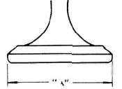


EXHAUST
|
Clearance (cold engine) |
0.16-0.20 mm (0.006-0.008 in) |
|
"A" head diameter |
26 ±0.1 mm (1.024± 0.0039 in) |
|
"8" face width |
2.3 mm (0.0906 in) |
|
"C" seat width |
1.0± 0.1 mm (0.0394 ±0.0039 in) |
|
"D" margin thickness (minimum) |
1.0 ±0.2 mm (0.0394 ±0.0079 in) |
|
Stem diameter (O.D.) |
6 -0.025 -0.040 mm (0.2362 -0.0010 -0.0016 in) |
|
Guide diameter (I.D.) |
6 +0.012 0 mm (0.2362 +0.0005 -0 in) |
|
Stem-to-guide clearance |
0.025—0.052 mm (0.0010-0.0020 in) |
|
Cylinder and piston: |
|
|
Cylinder material |
Aluminum alloy |
|
Cylinder liner |
Pressed in; special cast iron |
|
Bore size: |
|
|
Cylinder taper limit |
0.05 mm (0.0020 in) |
|
Cylinder out-of-round limit |
0.01 mm (0.0004 in) |
|
Piston clearance: |
|
|
Piston rings: |
Top |
2nd |
Oil |
|
|
Design |
Barrel |
Taper |
Expander |
|
|
End gap (installed): |
standard |
0.15-0.35 mm (0.0059 -0.0138 in) |
0.15-0.35 mm (0.0059-0.0138 in) |
0.3-0.9 mm (0.0118-0.035 in) |
|
limit |
1.0 mm (0.0394 in) |
1.0 mm (0.0394 in) |
1.5 mm (0.0591 in) |
|
|
Side clearance: |
standard |
0.03—0.07 mm (0.0012-0.0028 in) |
0.02-0.06 mm (0.008-0.0024 in) |
- |
|
limit |
0.15 mm (0.0059 in) |
0.15 mm (0.0059 in) |
- |
|
Crankshaft: |
||
|
Crank journal/bearing oi! clearance |
0.040~ 0.064 mm (0.0016-0.0025 in) |
|
|
Main journal run out (maximum) |
0.03 mm (0.0012 in) |
|
|
Connecting rods: |
||
|
Rod bearing oil clearance |
0.03 -0.09 mm (G.0012-0.0035 in) |
|
|
Oil pump: |
||
|
Housing-to-outer rotor clearance |
0.09-0.15 mm (0.0035- 0.0059 in) |
|
|
Outer rotor-to-inner rotor clearance |
0.03-0.09 mm (0.0012- 0.0035 in) |
|
|
Clutch: |
||
|
Frictionpplate: |
thickness/q'ty |
3.0 mm (0.12in)/8 |
|
Clutch plate: |
thickness |
1.6 mm (0.063 in)/7 |
|
Clutch spring: |
length/q'tv |
41.2 mm (1.622 in)/5 |
|
Clutch lever freeplay (at lever pivot point) |
2 -3 mm (0.08-0.12 in) |
|
General Torque Specifications and Conversion factors
General Torque Specifications and Conversion factorsGeneral torque specifications
This chart specifies torque for standard fasteners with standard I.S.O. pitch threads. Torque specifications for special components or assemblies are included in the applicable sections of this book. To avoid warpage, tighten multi-fastener assemblies in a criss-cross fashion, in progressive stages, until full torque is reached. Unless otherwise specified, torque specifications call for clean, dry threads. Components should be at room temperature.

|
A (Nut) |
B (Bolt) |
General torque specifications |
|
|
m-kg |
ft-lb |
||
|
10 mm |
6 mm |
0.6 |
4.5 |
|
12 mm |
8 mm |
1.5 |
11 |
|
14 mm |
10 mm |
3.0 |
22 |
|
17 mm |
12 mm |
5.5 |
40 |
|
19 mm |
14 mm |
8.5 |
51 |
|
22 mm |
16 mm 13.0 |
94 |
|
CONVERSION TABLES
|
METRIC TO INCH SYSTEM |
|||
|
|
KNOWN |
MULTIPLIER |
RESULT |
|
TORQUE |
m-kg |
7.233 |
ft-lb |
|
m-kg |
86.80 |
in-lb |
|
|
cm-kg |
0.0723 |
ft-lb |
|
|
cm-kg |
0.8680 |
in-lb |
|
|
WT. |
kg |
2.205 |
lb |
|
9 |
0.03527 |
oz |
|
|
FLOW / DISTAMCE |
km/lit |
2.352 |
mpg |
|
km/hr |
0.6214 |
mph |
|
|
km |
0.6214 |
mi |
|
|
m |
3.281 |
ft |
|
|
m |
1.094 |
yd |
|
|
cm |
0.3937 |
in |
|
|
mm |
0.03937 |
in |
|
| VOLUME/
CAPACITY |
cc (cm3) |
0.03382 |
oz (US liq) |
|
cc (cm ) |
0.06102 |
cu. m |
|
|
lit (liter) |
2.1134 |
pt (US liq) |
|
|
lit (liter) |
1.057 |
qt (US liq) |
|
|
lit (liter) |
0.2642 |
gal (US liq) |
|
| MISC. |
kg/mm |
56.0C7 |
lb/in |
|
kg/cm |
14.2234 |
psi (lb/in2) |
|
| Centigrade (°C) | 9/5(°C) + 32 | Fahrenheit (° F) | |
|
INCH TO METRIC SYSTEM |
|||
|
|
KNOWN |
MULTIPLIER |
RESULT |
| TORQUE |
ft-lb |
0.13826 |
m-kg |
|
in-lb |
0.01152 |
m-kg |
|
|
ft-lb |
13.831 |
cm-kg |
|
|
in-lb |
1.1521 |
cm-kg |
|
|
WT. |
lb |
0.4535 |
kg |
|
oz |
28.352 |
g |
|
| FLOW /
DISTANCE |
mpg |
0.4252 |
km/lit |
|
mph |
1.609 |
km/hr |
|
|
mi |
1.609 |
km |
|
|
ft |
0.3048 |
m |
|
|
yd |
0.9141 |
m |
|
|
in |
2.54 |
cm |
|
|
in |
25.4 |
mm |
|
|
VOLUME / CAPACITY |
oz (US liq) |
29.57 |
cc (cm ) |
|
cu.in |
16.387 |
cc "cm ) |
|
|
pt (US liq) |
0.4732 |
lit (liter) |
|
|
qt (US liq) |
0.9461 |
lit (liter) |
|
|
gal (US liq) |
3.785 |
lit (liter) |
|
|
MISC. |
lb/in |
0.017855 |
kg/mm |
|
psi (lb/in ) |
0.07031 |
kg/cm2 |
|
|
Fahrenheit (°C) |
5/9(°F-32) |
Centigrade (°F) |
|
|
DEFINITION OF TERMS: |
||
|
m-kg |
= |
Meter-kilogram(s) (usually torque) |
|
9 |
= |
Gram(s) |
|
kg |
= |
Kilogram(s) (1,000 grams) |
|
lit |
= |
Liter(s) |
|
km/lit |
= |
Kilometer(s) per liter (fuel consumption) |
|
cc |
= |
Cubic centimeter(s) (cm3) (volume or capacity) |
|
kg/mm |
= |
Kilogram(s) per millimeter (usually spring compression rate) |
|
kg/cm2 |
= |
Kilogram(s) per square centimeter (pressure) |
|
|
|||
Lubrication Diagrams
Lubrication DiagramsLUBRICATION DIAGRAM

|
|
> Pressure feed |
|
|
• Splashed |


Oil pressure information
Relief valve opening: 5 kg/cm3 (72 psi)
Bypass valve opening: 1 kg/cm2 (14 psi)
Engine sump oil quantity
Total: 2,900 cc (3.1 USqt)
With oil filter replacement: 2,500 cc (2.6 US qt)
Periodic oil change: 2,200 cc (2.3 US qt)


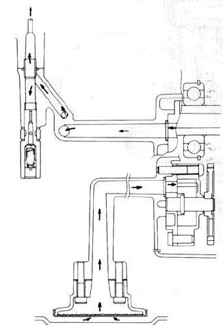

Cable Routing Diagrams
Cable Routing Diagrams


Diode Block
Diode Block
Parts Diagram -- Clutch
Parts Diagram -- Clutch xjcdadmin Fri, 06/18/2010 - 01:45PARTS ILLUSTRATIONS CLUTCH

Parts Diagram -- Transmission
Parts Diagram -- Transmission xjcdadmin Fri, 06/18/2010 - 01:45
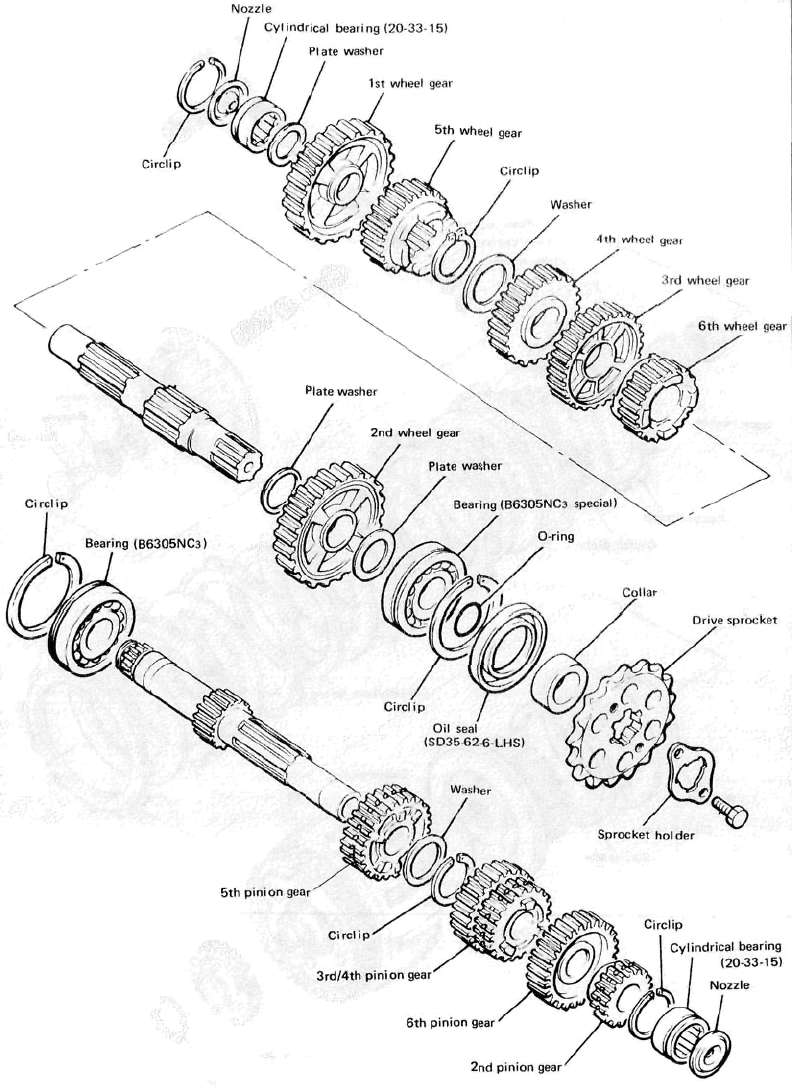
Parts Diagram -- Wheels
Parts Diagram -- Wheels xjcdadmin Fri, 06/18/2010 - 01:46FRONT WHEEL

REAR WHEEL
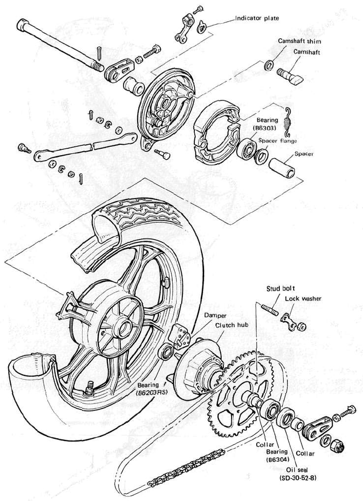
Parts Diagram -- Front Brake
Parts Diagram -- Front Brake xjcdadmin Fri, 06/18/2010 - 01:46FRONT BRAKE (MASTER CYLINDER)

FRONT BRAKE (CALIPER)

Torque Specifications
Torque Specifications xjcdadmin Fri, 06/18/2010 - 01:45|
Part to be tightened |
Part name |
Thread size |
Q'ty |
Tightening torque |
Remarks |
||
|
m-kg |
ft-lb |
||||||
|
ENGINE: |
|||||||
|
Cam shaft cap |
Bolt |
M6x 1.0 |
24 |
1.0 |
7.2 |
Tighten in 3-stages |
|
|
Cylinder head {cam chain) |
Stud bolt |
M6X1.0 |
4 |
0.5 |
3.6 |
Apply oil |
|
|
Cylinder head (Exhaust pipe) |
Stud bolt |
M6x 1.0 |
8 |
1.0 |
7.2 |
Apply oil |
|
|
Cylinder head |
Stud bolt |
M8X1.25 |
2 |
1.5 |
11.0 |
Apply oil |
|
|
Cylinder head |
Nut |
M8X1.25 |
2 |
2.0 |
14.5 |
||
|
Cylinder head |
Cap nut |
M8x 1.25 |
12 |
2.2 |
16.0 |
Apply oil |
|
|
Spark plug |
M12x1.25 |
4 |
2.0 |
14.5 |
|||
|
Cylinder head cover |
Bolt |
M6X1.0 |
12 |
1.0 |
7.2 |
||
|
Tachometer gear housing |
Bolt |
M6x 1.0 |
1 |
1.0 |
7.2 |
||
|
Cylinder |
Stud bolt |
M8X1.25 |
1 |
1.6 |
11.0 |
Apply oil |
|
|
Cylinder (YICS blind plug) |
Plug |
M12x 1.25 |
2 |
2.2 |
16.0 |
||
|
Cylinder and crankcase |
Nut |
M8x 1.25 |
1 |
2.0 |
14.5 |
||
|
Cylinder head and cylinder |
Nut |
M6 x 1.0 |
4 |
1.0 |
7.2 |
Cam chain (front & rear) |
|
|
Connecting rod and rod cap |
Nut |
M7 x 0.75 |
8 |
2.5 |
18.0 |
||
|
Camshaft and sprocket |
Bolt |
M7x1.0 |
4 |
2.0 |
14.5 |
||
|
Cam chain tensioner stopper bolt |
Bolt |
M6x1.0 |
1 |
0.6 |
4.3 |
|
|
|
Cam chain tensioner case and cylinder |
Bolt |
M6x 1.0 |
1 |
1.0 |
7.2 |
||
|
Cam chain tensioner case and cylinder |
Nut |
MB x 1.0 |
1 |
1.0 |
7.2 |
||
|
Cam chain tensioner lock nut |
Nut |
M8x1.25 |
1 |
0.9 |
6.5 |
||
|
Crankcase |
Plug |
MIOxl.25 |
1 |
1.0 |
7.2 |
|
|
|
Rotor housing and pump cover |
Screw |
M6x 1.0 |
1 |
0,7 |
5.1 |
||
|
Oil pump ass'y and crankcase |
Screw |
M6x1.0 |
3 |
0.7 |
5.1 |
||
|
Strainer housing and crankcase |
Bolt |
M6x 1.0 |
2 |
1.0 |
7.2 |
||
|
Strainer cover and crankcase |
Bolt |
M6x1.0 |
12 |
1.0 |
7.2 |
||
|
Filter cover and crankcase |
Union bolt |
M20x 1.5 |
1 |
1.5 |
11.0 |
||
|
Strainer cover |
Plug |
M14X1.5 |
1 |
4.3 |
31.0 |
||
|
Carburetor joint and Cylinder head |
Bolt |
M6x 1.0 |
8 |
1.0 |
7.2 |
||
|
Air filter |
Screw |
M5 x 0.8 |
4 |
0.5 |
3.6 |
||
|
Air filter |
Bolt |
M6 x 1.0 |
3 |
0.7 |
5.1 |
||
|
Exhaust pipe and cylinder head |
Nut |
M6x1.0 |
8 |
1.0 |
7.2 |
||
|
Exhaust pipe joint |
Bolt |
M8x1.25 |
6 |
2.0 |
14.5 |
||
|
Muffler |
Bolt |
M10x 1.25 |
2 |
2.5 |
18.0 |
||
|
Muffler protector |
Bolt |
M10x1.25 |
1 |
2.5 |
18.0 |
||
|
Muffler protector |
Screw |
M6x 1.0 |
2 |
i °:7 |
5.1 |
||
|
Crankcase |
Stud bolt |
M8x1.25 |
12 |
1.3 |
9.5 |
Apply oil |
|
|
Crankcase (upper and lower) |
Bolt |
M8xl.25 |
11 |
2.4 |
17.5 |
Apply oil |
|
|
Crankcase (upper and lower) |
Bolt |
M6x1.0 |
23 |
1.2 |
8.5 |
Apply oil |
|
|
Generator cover and crankcase |
Bolt |
M6x1.0 |
3 |
1.0 |
7.2 |
||
|
Bearing cover plate (crankcase right) |
Bolt |
M6x1.0 |
2 |
1.0 |
7.2 |
||
|
Bearing cover plate (crankcase left) |
Screw |
M6x 1.0 |
2 |
1.0 |
7.2 |
Use LOCKTITE |
|
|
Clutch cable holder |
Screw |
M6x1.0 |
1 |
1.0 |
7.2 |
||
|
Crankcase cover |
Bolt |
M6x1.0 |
13 |
1.0 |
7.2 |
||
|
Crankcase (Main gallary blind plug) |
Plug |
M20x1.5 |
2 |
1.2 |
8.5 |
Apply oil |
|
|
Clutch pressure plate |
Bolt |
M6x 1.0 |
5 |
0.8 |
5.8 |
||
|
Clutch boss |
Nut |
M20x 1.0 |
1 |
7.0 |
50.5 |
||
|
Drive sprocket |
Bolt |
M6x1.0 |
2 |
1.0 |
7.2 |
||
|
Cam shift |
Screw |
M5 x 0.8 |
1 |
0.7 |
5.1 |
Use LOCKTITE |
|
|
Stopper plate |
Bolt |
M6x1.0 |
1 |
1.0 |
7.2 |
||
|
Change pedal |
Bolt |
M6x 1.0 |
1 |
1.0 |
7.2 |
||
|
A.C. Generator |
Bolt |
M10x1.25 |
1 |
3.5 |
25.5 |
||
|
A.C. Generator (brush) |
Screw |
M6x1.0 |
2 |
0.8 |
5.8 |
||
|
A.C. Generator (rotor) |
Bolt |
M8 x 1.25 |
1 |
2.4 |
17.5 |
||
|
Pick up coil base |
Screw |
M6X1.0 |
2 |
0.8 |
5.8 |
||
|
Timing plate |
Screw |
M6 x 1.0 |
1 |
0.8 |
5.8 |
||
|
Starter motor |
Bolt |
M6x1.0 |
2 |
1.0 |
7.2 |
|
|
|
Neutral switch |
Screw |
M5x0.8 |
3 |
0.3 |
2.2 |
Use LOCKTITE |
|
|
Oil level gauge switch |
Bolt |
M6x 1.0 |
2 |
0.7 |
5.1 |
||
| Chassis: | |||||||
| Engine mounting Bolts Front, upper Front, under Rear, under |
Nut Bolt Nut |
M10 PI.25 M10 PI.25 M12 P1.25 |
1 2 1 |
4.2 4.2 7.0 |
30.5 30.5 50.5 |
||
| Engine Mounting Stay Front | Bolt | M8 P1.25 | 4 | 2.0 | 14.5 | ||
|
Handle crown & Steering shaft |
Bolt |
M14 P1.25 |
1 |
5.4 |
39.0 |
||
|
Handle crown & Inner tube |
Nut cap |
M8 PI .25 |
1 |
2.0 |
14.5 |
||
|
Handle crown&Handlebar holder |
Bolt |
M8 PI .25 |
4 |
2.0 |
14.5 |
||
|
Under bracket & Inner tube |
Bolt |
M12 P1.25 |
2 |
3.8 |
27.5 |
||
|
Front wheel shaft |
Nut Castle |
M14 P1.5 |
1 |
10.5 |
76.0 |
||
|
Front wheel Axle pinch bolt |
Nut salf locking |
M8 PI.25 |
2 |
2.0 |
14.5 |
||
|
Pivot shaft |
Nut |
M14 P1.5 |
1 |
9.0 |
65.0 |
||
|
Rear wheel shaft |
Nut castle |
M14 P1.5 |
1 |
10.5 |
76.0 |
||
|
Sprocket wheel |
Nut |
M10 P1.25 |
6 |
6.2 |
45.0 |
||
|
Rear shock absorber (Upper) |
Nut cap |
M10 P1.25 |
2 |
3.0 |
21.5 |
||
|
Rear shock absorber (Lower) |
Bolt |
M10 P1.25 |
2 |
3.0 |
21.5 |
||
|
Footrest |
Bolt |
M12 P1.25 |
2 |
7.0 |
50.5 |
||
|
Tension bar & Brake plate |
Bolt |
M8 P1.25 |
2.0 |
14.5 |
|||
|
Tension bar & Rear arm |
Bolt |
M8 P1.25 |
2.0 |
14.5 |
|||
|
Camshaft lever & Camshaft |
Bolt |
M6 P1.0 |
0.9 |
6.5 |
|||
|
Brake disc & Hub (Front) |
Bolt |
M8 P1.25 |
12 |
2.0 |
14.5 |
Lock washer |
|
|
Master cylinder & Brake hose (Front) |
Bolt union |
M10 P1.25 |
2.6 |
19.0 |
|||
|
Brake hose & Joint |
Bolt union |
M10 P1.25 |
2.6 |
19.0 |
|||
|
Caliper & Brake hose |
Bolt union |
M10 P1.25 |
2.6 |
19.0 |
|||
|
Caliper & Front fork (Front) |
M10 P1.25 |
4.5 |
32.5 |
||||
|
CaMper bleed screw (Front) |
M8 P1.25 |
0.6 |
4.3 |
||||
|
Front fender |
Bolt |
M8 P1.25 |
1.0 |
7.2 |
|||
|
Master cylinder cap |
Screw |
M5 P0.8 |
2 |
0.18 |
1.3 |
||
|
Muffler bracket & Frame |
Bolt |
M10 P1.25 |
4 |
4.2 |
30.5 |
||
|
Muffler brakcet & Muffler (rear footrest) |
Bolt |
M10 PI .25 |
2 |
4.5 |
32.5 |
||
|
Master cylin Master cylinder bracket |
Bolt |
M6 P1.0 |
2 |
0.9 |
6.5 |
||
|
Steering shaft & Ring nut |
Nut |
M25 P1.0 |
1 |
3.8 |
27.5 |
||
|
Brake pedal & Brake shaft |
Bolt |
M6 P1-0 |
1 |
0.9 |
6.5 |
||
|
Sensor & Fuel tank |
Bolt |
M6 P1.0 |
4 |
0.5 |
3.6 |
||
|
Rear arm end & rear arm |
Bolt |
M6 P1.0 |
2 |
0.6 |
4.3 |
||
Electrical Component Locations and Wiring Diagram
Electrical Component Locations and Wiring DiagramELECTRICAL COMPONENTS