Ignition System
Ignition SystemIGNITION SYSTEM
3 Main switch
7 Fuse "IGNITION" (10A)
8 "ENGINE STOP" switch
9 Pickup coil
10 T.C.I, unit
11 Ignition coil (#2, #3)
12 Ignition coil (#1, #4)
13 Sidestand relay
48 Battery
49 Fuse "MAIN" (30A)
DESCRIPTION
This model is equipped with a battery operated, fully transistorized, breakerless ignition system. By using magnetic pickup coils, the need for contact breaker points is eliminated. This adds to the dependability of the system by eliminating frequent cleaning and adjustment of points and ignition timing. The TCI (Transistor Control Ignition) unit incorporates an automatic advance circuit controlled by signals generated by the pickup coil. This adds to the dependability of the system by eliminating the mechanical advancer. This TCI system consists of two units; a pickup unit and an ignitor unit.
OPERATION
The TCI functions on the same principle as a conventional DC ignition system with the exception of using magnetic pickup coils and a transistor control box (TCI) in place of contact breaker points.
Pickup Unit
The pickup unit consists of two pickup coils and a flywheel mounted onto the crankshaft. When the projection on the flywheel passes a pickup coil, a signal is generated and transmitted to the ignitor unit. The width of the projection on the flywheel determines the ignition advance.

1 Pickup coils
Ignitor Unit
This unit controls wave form, duty control, switching, electronic ignition advance, etc. The duty control circuit reduces electrical consumption by controlling the duration of the primary ignition current.

The ignitor unit 1 also has a protective circuit for the ignition coil. If the ignition switch is on and the crankshaft is not turning, the protective circuit interrupts the current flow to the primary coil after a few seconds. When the crankshaft is turning, however, the ignitor unit sends current to the primary coil.
1. Remove:
• Seat
• Left side cover
• Panel
• Ignitor unit 1
TROUBLESHOOTING
1. Start engine and warm-up a while, then turn it off.

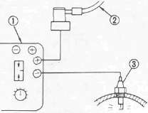
2. Connect Electro Tester (90890-03021) 1
2 Spark plug wire
3 Spark plug
3. Start engine and increase spark gap until misfire occurs (Test at various rpm between idle and red line.)
CAUTION:
Do not run the engine in neutral above 6,000 rpm for more than 1 or 2 seconds.
Minimum Spark Gap: 6 mm (0.24 in)
4. If ignition system becomes inoperative or engine misfires see the troubleshooting chart below:
Troubleshooting Chart
|
Check entire ignition connections. |
Poor connection ► |
Correct.
|
|
▼ OK |
||
|
Check battery voltage and specific gravity. |
Low voltage/specific gravity ► |
Recharge battery.
|
|
▼ OK |
||
|
Check fuse and fuse connections. |
Weak connection or open circuit ► |
Correct connection or replace fuse.
|
|
▼ OK |
||
Check ignition coil resistance (primary and secondary).Primary: 2.7Ω ± 10%at20°C (68°F) Secondary: 12 kΩ ± 20% at 20°C (68° F) |
If other than specified ► |
Replace ignition coil.
|
|
▼ OK |
If other than specified ► |
Replace pickup coil assembly.
|
|
Check pickup coil resistance. Pickup coil: 120Ω ± 10% at 20°C (68°F) |
||
|
▼ OK |
||
|
Check operation of sidestand switch and relay. |
Faulty ► |
Check sidestand relay sidestand switch, diode and neutral switch.
|
|
▼ OK |
||
|
TCI unit is faulty, replace unit. |
IGNITION COIL
1. Remove the fuel tank

2. Disconnect the ignition coil leads 1
2 No. 2 and No. 3 cylinder ignition coil

3. Measure the primary coil resistance
Primary Coil Resistance:
O to R/W lead connector
Gy to R/W lead connector
2.7Ω ± 10% at 20°C (68°F)

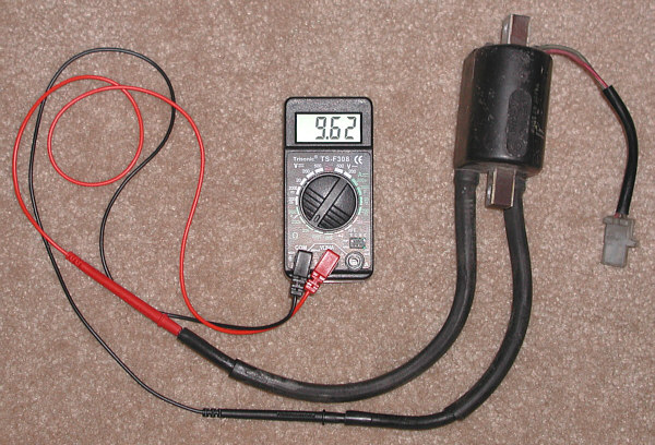
4. Measure secondary coil resistance
Secondary Coil Resistance:
12kΩ ±20% at 20°C (68°F)

5. Connect:
Electro tester 1
Fully charged battery 2 (to ignition oil leads)
3 No. 1 (Rear) cylinder high tension cord
4 Ground
5 R/W lead
6 O lead
6. Measure the ignition coil minimum spark gap Turn the spark gap adjuster and increase the gap to the maximum limit unless misfire occurs first.
Minimum Spark Gap: 6 mm (0.24 in)
PICKUP COIL
1. Remove:
• Left side cover
• Panel
2. Disconnect pickup coil wires from TCI unit wires.

3. Measure the pickup coil resistance. Use pocket tester.
Pickup Coil Resistance:
No. 1 and No. 4 cylinder (O — B)
No, 2 and No. 3 cylinder (Gy - B)
120Ω ± 10% at 20°C (68°F)
SIDESTAND RELAY

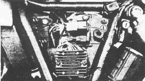
1. Remove:
• Left side cover
•Sidestand relay 1
2. Check the relay contacts

Use 12V battery 3 and Pocket Tester (90890-03112).
Battery Connected: ∞ 2
Battery Disconnected: 0Ω 1
SPARK PLUG
1. Check condition and replace if burned or fouled. Clean and regap as necessary.
CAUTION:
Be sure to use plugs of proper type
DR8ES-L (NGK) X24ESR-U (NIPPONDENSO)

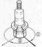
Electrode Gap 1 :
0.6 ~ 0.7 mm (0.024 - 0.028 in)
2. Install spark plug
Spark Plug: 17.5 Nm (1.75m*kg, 12.5ft-lb)

1 Finger tighten
2 Plug wrench tighten

