Chapter 1, GENERAL INFORMATION and SPECIAL TOOLS
Chapter 1, GENERAL INFORMATION and SPECIAL TOOLSGENERAL INFORMATION
MOTORCYCLE IDENTIFICATION

VEHICLE IDENTIFICATION NUMBER
The vehicle identification number is stamped into the right side of the frame.
NOTE:
The vehicle identification number is used to identify your motorcycle and may be used to register your motorcycle with the licensing authority in your state or province.
Starting Serial Number:
XJ750XN JYA1FL00 * FA000101

ENGINE SERIAL NUMBER
The engine serial number is stamped into the right side of the engine.
NOTE:
The first three digits of these numbers are for model identifications; the remaining digits are the unit production number.
Starting Serial Number:
XJ750XN 1FL-000101
NOTE:
Designs and specifications are subject to change without notice.

IMPORTANT INFORMATION
ALL REPLACEMENT PARTS
1. We recommend to use Yamaha genuine parts for all replacements. Use oil and/or grease recommended by Yamaha for assembly and adjustment.
GASKETS, OIL SEALS, AND O-RINGS
1. All gaskets, seals, and O-rings should be replaced when an engine is overhauled. All gasket surfaces, oil seal lips, and O-rings must be cleaned.
2. Properly oil all mating parts and bearings during reassembly. Apply grease to the oil seal lips.

LOCK WASHERS/PLATES AND COTTER PINS
1. All lock washers/plates (1) and cotter pins must be replaced when they are removed. Lock tab(s) should be bent along the bolt or nut flat(s) after the bolt or nut has been properly tightened.


BEARINGS AND OIL SEALS
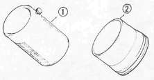
1. Install the bearing(s) (1) and oil seal(s) (2) with their manufacturer's marks or numbers facing outward. (In other words, the stamped letters must be on the side exposed to view.) When installing oil seal(s), apply a light coating of light-weight lithium base grease to the seal lip(s). Oil the bearings liberally when installing.
CAUTION:
Do not use compressed air to spin the bearings dry. This causes damage to the bearing surfaces.
CIRCLIPS
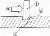
1.All circlips should be inspected carefully before reassembly. Always replace piston pin clips after one use. Replace distorted circlips. When installing a circlip © , make sure that the sharp-edged corner © is positioned opposite to the thrust (3) it receives. See the sectional view.

4.Shaft
SPECIAL TOOLS
The proper special tools are necessary for complete and accurate tune-up and assembly. Using the correct special tool will help prevent damage caused by the use of improper tools or improvised techniques.
FOR TUNE UP

1. Inductive Tachometer P/N. 90890-03113 This tool is needed for detecting engine rpm.

2. Inductive Timing Light P/N. 90890-03109 This tool is necessary for checking ignition timing.

3. Compression Gauge P/N. 90890-03081
This gauge is used to measure the engine compression.

4. Fuel Level Gauge P/N. 90890-01312 This gauge is used to measure the fuel level in the float chamber.

5. Vacuum gauge P/N. 90890-03094 This gauge is needed for carburetor synchronization.
FOR ENGINE SERVICE

1. Universal Clutch Holder P/N. 90890-04086 This tool is used to hold the clutch when removing or installing the clutch boss locknut.

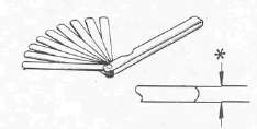
2. Thickness Gauge P/N. 90890-01399
This gauge is needed for measuring the valve clearance.
* Less than 8 mm (0.31 in)

3. Valve Spring Compressor P/N. 90890-04019- (1)
Attachment P/N. 90890-04108- (2)
This tool is needed to remove and install the valve assemblies.

4. Valve Guide Remover (5.0 mm) P/N. 90890-04097
This tool is used to remove the valve guides.

5. Valve Guide Reamer (5.0 mm) P/N. 90890-04099
This tool is used to rebore the new valve guide.

6. Valve Guide Installer P/N. 90890-04098
This tool is needed to install the valve guides properly.

7. Valve Seat Cutter Set P/N.YM-91043
This tool is needed to resurface the valve seat.

8. Armature Shock Puller P/N. 90890-01290- (1)
Weight P/N. 90890-01291 - (2)
These tools are used to remove the A.C.G. shaft.

9. Rotor Holding Tool P/N. 90890-04043
This tool is used to hold the A.C. Generator rotor during removal and installation.

10. Rotor Puller
P/N. 90890-01080 This tool is needed to remove the A.C. Generator rotor.

11. Rotor Puller Attachment
P/N. 90890-04052 This tool is needed when removing the A.C. Generator rotor together with the rotor puller.

12. Water Pump Seal Installer
Handle P/N. 90890-04058- (1)
Adapter P/N. 90890-04078- (2)
This tool is needed for proper installation of the water pump seal.

13. Torx Driver
#40 P/N. 90890-04049 - (1)
This tool is used to loosen or tighten the middle gear bearing retainer bolt.
#30 P/N. 90890-05245 - (2)
This tool is used to loosen or tighten the A.C.G. shaft cover.

14. Plastigauge Set "Green"
P/N. YU-33210 This gauge is needed to measure the clearance for the connecting rod bearing.

15. Yamaha Bond No. 1215
P/N. 90890-85505
This sealant (bond) is used for crankcase mating surfaces, etc.
FOR SHAFT DRIVE SERVICE

1. Middle Drive Pinion Holder
P/N. 90890-04051
This tool is needed when measuring gear lash.

2. Dial Gauge
P/N. 90890-03097
This gauge is used to measure gear lash.

3. Damper Spring Compressor
P/N. 90890-04090
This tool is needed to disassemble and reassemble the middle gear damper.

6. Middle-Drive-Shaft-Bearing-Retainer Wrench
P/N. 90890-04057
This tool is used to loosen or tighten the bearing retainer.

7. Final Gear Holding Tool
P/N. 90890-01254
This tool is needed when measuring gear lash.

8. Final-Drive Gear Lash Measurement Tool
P/N. 90890-01230
This tool is used to measure gear lash.

9. Middle and Final Gear Holding Tool
P/N. 90890-01229
This tool is used when measuring gear lash.

10. Final Drive Shaft Bearing Retainer Wrench
P/N. 90890-04050
This tool is used to remove and install the bearing retainer.
FOR CHASSIS SERVICE

1.T-Handle
P/N. 90890-01326- (1)
Damper rod holder 22 mm
P/N. 90890-01365- (2)
This tool is used to loosen and tighten the front fork cylinder holding bolt.

2. Front Fork Seal Driver (weight)
P/N. 90890-01367-(1)
Adapter (38 mm)
P/N. 90890-01372 -(2)
These tools are used when installing the fork seal.

3. Ring Nut Wrench
P/N. 90890-01268
This tool is used to loosen and tighten the steering ring nut.
FOR ELECTRICAL COMPONENTS

1. Electro Tester
P/N. 90890-03021
This instrument is necessary for checking the ignition system components.

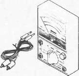
2. Pocket Tester
P/N. 90890-03112
This instrument is invaluable for checking the electrical system.