Chapter 4. Carburetion
Chapter 4. Carburetion xjcdadmin Mon, 05/17/2010 - 18:27CARBURETOR
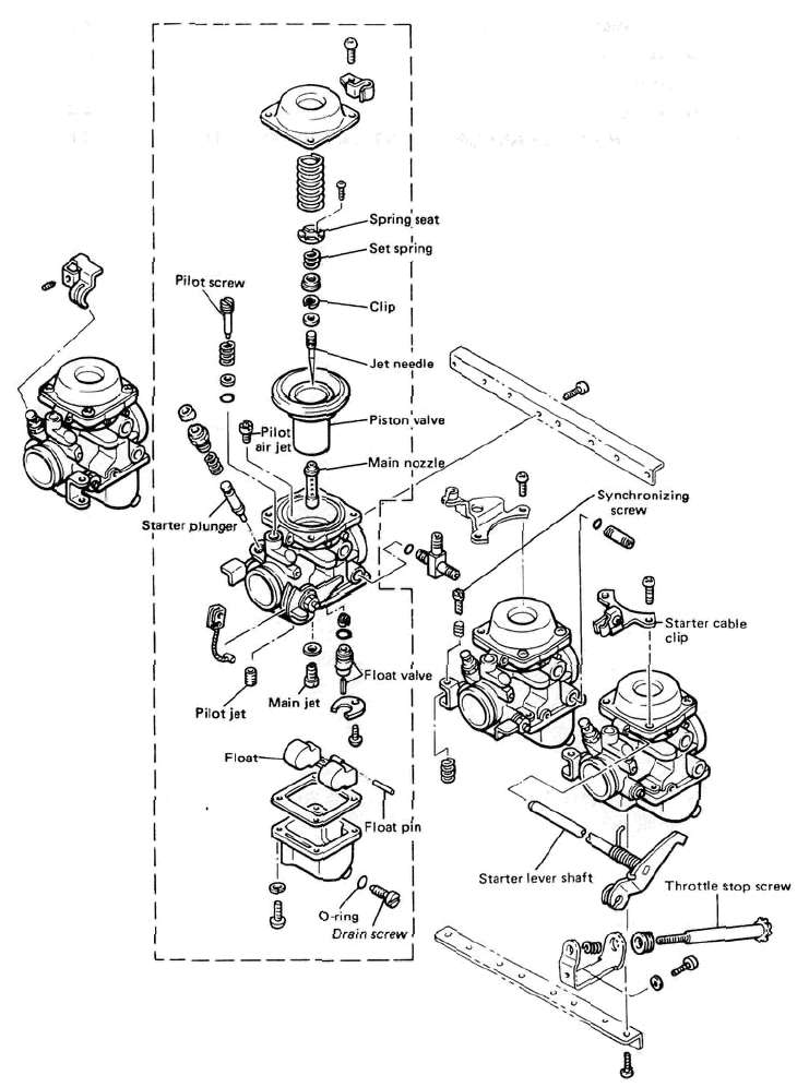
A. Section view

B. Specifications
|
Main jet |
# 112.5 |
|
Jet needle |
4GZ11 |
|
Needle jet |
O-S |
|
Starter jet |
#35 |
|
Fuel level |
2+ 1 mm{0.079±0039in) |
|
Pilot screw |
Preset |
|
Float valve seat |
<J> 2.0 |
|
Engine idle speed |
1,200 r/min |
CAUTION:
The pilot screw settings are adjusted for maximum performance at the factory with the use of specialized equipment. Do not attempt to change these settings. If all other engine systems are functioning correctly, any changes will decrease performance and cause increased exhaust emissions.
Disassembly and reassembly
Disassembly and reassembly xjcdadmin Mon, 05/17/2010 - 21:26
CAUTION:
Separation of the carburetors is not recommended. Usual disassembly for cleaning and inspection does not require separation of the carburetors. The carburetor body support screws are locked with a locking compound such "LOCTITE". If the carburetors are separated, misalignment will result.
1. Loosen the starter lever securing screws and remove the starter lever shaft.

2. Remove the vacuum chamber cover and remove the spring and diaphragm (vacuum piston).
NOTE:
Note that there is the tab on the rubber diaphragm. There is the matching recess in the carburetor body for the diaphragm tab.

3. Remove the pilot air jet.

I. Pilot air jet
4. Remove the screws holding the float chamber cover and remove the cover. The main and pilot jets are located in the float bowl. Remove the jets if necessary.


1. Pilot jet 2. Main jet
5. Pull out the float pivot pin. Remove the float assembly. Be careful to not lose the float valve under the float arm. Remove the float valve seat.

1. Float valve seat
6. Reasemble in reverse order. Pay close attention to the installation of the vacuum piston diaphragm and the location of each jet.
7. If the carburetors should be separated, care must be taken so that they are put together in place according to the following procedures:
a. Place the carburetors on a surface plate and install the lower support plate. Apply a thread locking compound such as "LOCTITE" and tighten the screws securely while holding the carburetor body.

1. Lower support plate 2. Surface plate
NOTE:
When reassembling, the surface plate should be used for the proper carburetor alignment.
b. Install the upper support plate. Apply a thread locking compound such as "LOCTITE" to the support screw threads and tighten the screws securely.
Inspection and Adjustment
Inspection and Adjustment xjcdadmin Mon, 05/17/2010 - 22:181. Examine the carburetor body and fuel passages. If contaminated, wash the carburetor in a petroleum-based solvent. Do not use caustic carburetor cleaning solutions. Blow out all passages and jets with compressed air.
2. Examine the condition of the floats. If the floats are damaged, they should be replaced.
3. Inspect the float needle valve and seat for wear or contamination. Replace these components as a set.

4. Inspect the vacuum piston and rubber diaphragm. If the piston is scratched or the diaphragm is torn, the assembly must be replaced.

1. Vacuum piston 3. Set spring
2. Needle Jet
5. Inspect the starter plunger for damage, If damaged, replace.

E. Adjustment
Fuel level
NOTE:
Before checking the fuel level, note the following:
1. Place the motorcycle on a level surface.
2. Adjust the motorcycle position by placing a suitable stand or a garage jack under the engine so that the carburetor is positioned vertically.
1. Connect the level gauge adapter (special tool) to the carburetor drain hole.
2. Connect the level gauge (special tool) or a vinyl pipe of 6 mm (0.24 in) in inside dia. to the level gauge adapter.
3. Set the gauge as shown and loosen the drain screw.

1. Level gauge adapter 2. Level gauge 3. Drain screw
4. Start the engine and stop it after a few minutes of running. This procedure is necessary to obtain the correct fuel level. Make sure the fuel petcock is "ON" or "RES" position.
5. Note the fuel level and bring the gauge to the other end of the carburetor line and repeat step 4 above. Note the fuel level again and compare it with the previous gauge reading. They should be equal. If not, place a suitable size of wooden piece or the life under the center stand and adjust.

6. Check the fuel level one by one. The level should be in the specified range.
Fuel level: 2 ± 1 mm (0.079 ± 0.039 in) below from the carburetor mixing chamber body edge.

7. If the fuel level is incorrect, remove the carburetor assembly from the motorcycle and check the fuel valve(s) and float assembly(s) for damage.
8. If no damage is found, correct the fuel level by slightly bending the float arm tang. Recheck the fuel level.

1. Float arm tang


