Chapter 2, PERIODIC MAINTENANCE
Chapter 2, PERIODIC MAINTENANCECHAPTER 2. PERIODIC INSPECTIONS AND ADJUSTMENTS
INTRODUCTION
This chapter includes all information necessary to perform recommend inspection
and adjustments. These preventative maintenance procedures, if followed, will
insure more reliable vehicle operation and a longer service life. The need for costly
overhaul work will be greatly reduced. This information applies not only to vehicles
already in service, but also to new vehicles that are being prepared for sale. Any
service technician performing preparation work should be familiar with this entire chapter.
Fairing, Fuel Tank and Oil Cooler Removal
Fairing, Fuel Tank and Oil Cooler RemovalFAIRING REMOVAL
The fairing assembly must be removed to perform maintenance as well as major overhauling procedures. Some maintenance procedures require that only part of the fairing assembly be removed. Yamaha recommends, however, that the entire fairing assembly be removed whenever the motorcycle is serviced. This will ensure that the fairing is not damaged or unnecessarily marred.
The following table lists those fairing components that must be removed to gain access to a particular area or component:
|
|
Sections to be removed |
|
||||||||||
|
|
1 |
2 |
3 |
4 |
5 |
6 |
7 |
8 |
9 |
10 |
NOTE |
|
|
ENGINE |
A. Turbo Charger Unit |
|
|
|
o |
|
|
|
|
|
|
need not be removed, but servicing procedures will be much easier |
|
B. Valve Clearance Adjustment |
o |
o |
o |
|
o |
o |
o |
o |
o |
|
|
|
|
C. Ignition Timing |
|
|
|
o |
|
|
|
|
|
|
|
|
|
D. Air Cleaner |
o |
|
|
|
|
|
|
|
|
|
|
|
|
E. Carburetor |
o |
o |
o |
o |
|
|
|
|
|
|
|
|
|
F. Engine Oil |
o |
|
|
|
|
|
|
|
|
|
|
|
|
Q. Final Gear Oil |
|
|
|
|
|
|
|
|
|
|
|
|
|
H. Compression Pressure Measurement |
|
|
|
|
|
|
|
|
|
|
|
|
|
1. Clutch Adjustment |
|
|
|
|
|
|
|
|
|
|
|
|
|
CHASSIS |
A. Fuel Cock |
o |
o |
o* |
o* |
|
|
|
|
|
|
*Loosen the securing bolts |
|
B. Front and Rear Brake |
|
|
|
|
|
|
|
|
|
|
|
|
|
C. Tubeless Tires and Aluminium Wheels |
|
|
|
|
|
|
|
|
|
|
|
|
|
D. Front Fork Oil Change |
|
|
|
|
|
|
|
|
|
|
|
|
|
E. Rear Shock Absorber |
|
|
|
|
|
|
|
|
|
o |
|
|
|
F. Steering Head Adjustment |
|
|
|
|
|
|
|
|
|
o |
|
|
|
G. Cable Inspection and Lubrication |
o |
|
o |
|
|
|
|
|
|
|
Clutch cable inspection |
|
|
H. Throttle Cable and Grip Lubrication |
o |
|
o |
|
|
|
|
|
|
|
|
|
|
1. Rear Arm Pivot Bearings |
|
|
|
|
|
|
|
|
|
|
|
|
|
J. Brake and Change Pedals/Brake and Clutch Lever |
|
|
|
|
|
|
|
|
|
|
|
|
|
K. Center and Side Stand Pivots |
|
|
|
|
|
|
|
|
|
|
|
|
|
ELECTRICAL |
A. Battery |
o |
|
o |
|
|
|
|
|
|
|
|
|
B. Spark Plug |
|
|
|
|
|
|
|
|
|
|
|
|
|
C. Headlight |
|
|
|
|
|
|
|
|
o |
|
|
|
|
D. Fuse |
o |
|
|
|
|
|
|
|
|
|
|
|
1 SEAT

2 FUEL TANK

3 SIDE PANEL

4 LOWER PANEL

5 UPPER PANEL (Right)

6 UPPER PANEL (Left)

7 WINDSCREEN

8 HEADLIGHT NACELLE

9 FRONT FLASHER LIGHTS


10 REAR MOLDING

Fairing Removal
1. Remove the seat.
To open the seat lock, insert the key in the lock. Then, turn it clockwise and pull the lever backward.
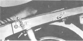
1. Open 2. Pull
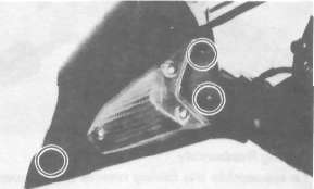
2. Remove the lower panel securing bolts (3X2) and remove the lower panel as one piece.


3. Remove the front securing bolts (2) and the side securing bolts (2).

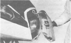
4. Remove the side panels as one piece. Grasp the panels on either side where the panels are joined to the frame. Pull the male connectors out; then pull the rear of the panels up.

5. Remove the headlight nacelle.

6. Remove the left and right front flashers (3X2); disconnect the lead couplers.
7. Remove the windscreen with the rear view mirrors (2X2).

8. Remove the two clips.

9. Remove the left and right upper panels.

10. Remove the securing bolts (4) and remove the rear molding while prying the ends apart.

Fairing Reassembly
To reassemble the fairing reverse the removal procedure.
Fuel Tank Removal
1. Remove the fuel tank securing bolt.

2. Disconnect the overflow pipe and emergency engine stop switch lead connecter.
3. Disconnect the fuel lines.
4. Remove the fuel tank.
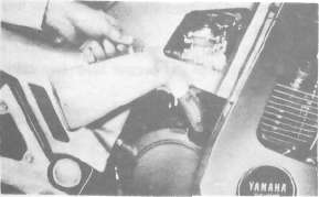
Oil Cooler Removal
1. Place an open container under the engine.
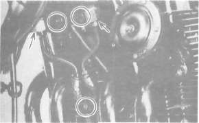
2. Remove the oil cleaner cap bolt.

3. Remove the spacer securing bolt.

4. Loosen the oil hose fitting nuts (2); then remove the oil cooler holding bolts (2) and the clamp bolt.
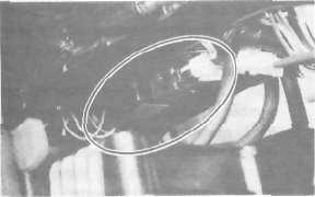
5. Remove the oil cooler assembly, pulling down and then away from the motorcycle.

Oil Cooler Installation
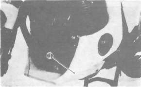
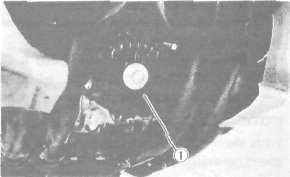
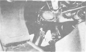
1. Install a new "O-ring" and install the oil cooler spacer to the crankcase. Make sure the "O-ring" is positioned properly.

1.O-ring
2. Tighten the spacer securing bolt.
Tightening torque:
50 Nm (5.0m.kg, 36 ft-lb)
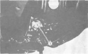
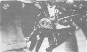
3. Install the oil filter element into the filter cover and install a new "O-ring". Make sure the "O-ring" is positioned properly.

1. O-ring
4. Tighten the oil cleaner cap bolt.
Tightening torque:
15 Nm (1.5 mkg, 11 ft-lb)
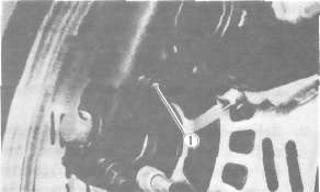
5. Tighten the oil cooler holding bolts (2).
Tightening torque:
10 Nm (1.0 m-kg, 7.2 ft-lb)
6. Tighten the clamp bolt.
Tightening torque: 10 Nm (1.0 m-kg, 7.2 ft-lb)
7. Tighten the oil hose fitting nuts (2).
Tightening torque: 45 Nm (4.5 m-kg, 32 ft-lb)
MAINTENANCE INTERVALS CHARTS
MAINTENANCE INTERVALS CHARTSProper periodic maintenance is important. Especially important are the maintenance services
related to emissions control. These controls not only function to ensure cleaner air but
are also vital to proper engine operation and maximum performance. In the following tables
of periodic maintenance, the services related to emissions control are grouped separately.
PERIODIC MAINTENANCE EMISSION CONTROL SYSTEM
|
NO. |
ITEM |
REMARKS |
INITIAL RREAK-IN |
THEREAFTER EVERY |
||
|
1.000 km |
5.000 km |
4.000 km |
8,000 km |
|||
|
1 |
Valve Clearance |
Check and adjust valve clearance when engine is cold. |
|
o |
|
o |
|
2 |
Spark plug |
Check condition. Adjust gap. Clean. |
|
o |
o |
Replace every |
|
3 |
Crankcase Ventilation |
Check ventilation hose 'or cracks or damage. |
|
o |
|
o |
|
4 |
Fuel Line |
Check fuel hose and vacuum pipe for cracks or damage. |
|
o |
|
o |
|
5 |
Intake/Exhaust System |
Check for leakage. Retighten as necessary. |
|
o |
o |
|
|
6 |
Idle Speed |
Check and adjust engine idle speed. |
|
o |
o |
|
| 7 |
Carburetor Synchronization |
Adjust synchronization of carburetors. |
|
o |
o |
|
GENERAL MAINTENANCE/LUBRICATION
|
NO'. |
ITEM |
REMARKS |
TYPE |
INITIAL BREAK-IN |
THEREAFTER EVERY |
|||
|
1,000 km |
5.000 km |
4,000 km |
8,000 km |
16.000 km |
||||
|
1 |
Engine Oil |
Warm up engine before draining |
Yamalube 4 cycle oil or SAE 2OW40 type SE motor oil |
o |
o |
o |
|
|
|
2 3 |
Oil Filter |
Replace |
— |
o |
o |
|
o |
|
|
Air Filter |
Clean with compressed air. |
- |
|
o |
|
o |
|
|
|
4 |
Brake System |
Adjust free play. Replace pads if necessary. (Front) Replace shoes if necessary (Rear) |
- |
o |
o |
o |
|
|
|
5 |
Clutch |
Adjust free play. |
- |
o |
o |
o |
|
|
|
6 |
Final Gear Oil |
Replace |
SAE 80 API "GL-4" Hypoid gear oil |
o |
|
|
o |
|
|
7 |
Control and Meter Cable |
Apply chain lube thoroughly. |
Y.irTidhj chain and cable lube or SAE 10W 30 motor oil |
o |
o |
o |
|
|
NOTE. 1. The air filter should be cleaned more often than at specified intervals if machine is operated in extremely dusty areas. 2- The lubrication chart must be adhered to strictly. Observe the following service hints to ensure that the oil will meet the demands placed on it by the engine.
Observe all periodic inspections as outlined. Use only the oil grade* specified. Keep the oil level at the specified level.
|
NO |
ITEM |
REMARKS |
TYPE |
INITIAL BREAK-IN |
THEREAFTER EVERY |
|||
|
1,000 km |
5.000 km |
4.000 km |
8.000 km |
16,000 km |
||||
|
8. |
Rear Arm Pivot Bearing |
Check bearings assembly for looseness. |
Medium weight bearing grease. |
|
|
|
|
Repack |
|
9 |
Centre- and Side- stand Pivots |
Apply lightly |
Yamaha chain and cable lube |
|
O |
o |
|
|
|
10. |
Front Fork Oil |
Drain completely. Refill to specification |
Yamaha fork oil 10 wt or equivalent |
|
|
|
|
O |
| 11, |
Steering Ball Bearing and Race* |
Check bearings assembly for looseness. |
Medium weight wheel bearing grease |
|
O |
o |
|
Repack |
|
12. |
Wheel Bearings |
Check bearings for smooth rotation. |
- |
|
O |
o |
|
|
|
13. |
Battery |
Check specific gravity. |
- |
|
O |
o |
|
|
|
14. |
Change/ Brake Pedal shaft Pivot |
Apply lightly |
Yamaha chain and cable lube |
|
O |
o |
|
|
|
15. |
AC Generator |
Replace generator brushes. |
- |
|
|
|
|
Replace |
|
16. |
Apply lightly |
Apply lightly |
Yamaha chain and cable lube |
|
o |
o |
|
|
Engine Maintenance
Engine MaintenanceENGINE
A. Valve clearance adjustment
NOTE:
Valve clearance must be measured with the engine and at room temperature.
1. Remove the seat, fairing components, and fuel tank. See page 35.
2. Remove the horn, flasher relay, emergency engine stop relay and spark plug lead wires.
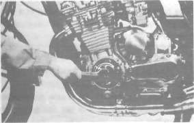
3. Remove the cylinder head cover and left crankcase cover (pick-up base cover). Care should be taken to not scratch or damage the gasket sealing surfaces.
4. Turn the crankshaft with the nut on the left end of the crankshaft to turn the cams. The proper position of the cam when measuring the valve clearance is with the cam lobe directly opposite the valve lifter.
5. Insert a feeler gauge between the valve lifter and the camshaft base circle,
Intake valve clearance (cold): 0.11-0.15 mm (0.004- 0.006 in)
Exhaust valve clearance (cold): 0.16-0.20 mm (0.006- 0.008 in)
Adjustment
Valve clearance is adjusted by replacing the adjusting pad on the top of the valve lifter. Adjusting pads are available in 25 thicknesses ranging from No. 200 (2.000 mm) to No. 320 (3.20 mm) in steps of 0.05 mm. The thickness of each pad is marked on the pad face that contacts of the valve lifter (not the cam). Adjustment of the valve clearance is accomplished as follows:
1. Determine valve clearance (feeler gauge measurement.)
2. Remove adjusting pad and note number.
3. Select proper pad from appropriate chart (intake or exhaust chart).
4. Install new pad and check installed clearance.
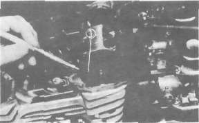
Procedure
1. Measure valve clearance. If clearance is incorrect, record the measured amount of clearance. This must be measured carefully.
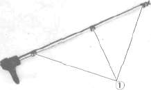
2. There is a slot in the valve lifter. This slot must be positioned opposite the blades of the tappet adjusting tool before the tools is installed.
3. Turn the cam until the lobe fully depresses the valve lifter and opens the valve. Install the tappet adjusting tool as shown to hold the lifter in this depressed position.
NOTE:
The tappet adjusting tool is fastened to the cylinder head securely using one alien screw such as one used to install the cylinder head cover. Make sure that the tool contacts the lifter only, and not the pad.
CAUTION:
If the cam lobe touches the tappet adjusting tool, the stress may fracture the cylinder head. DO NOT ALLOW THE CAM TO CONTACT THE TAPPET ADJUSTING TOOL.
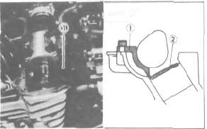
1 tappet adjusting tool 2. Adjusting pad
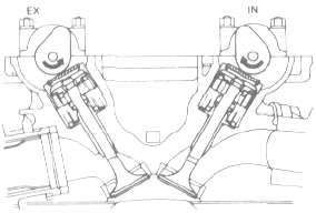
4. Carefully rotate the cam so that the pad can be removed. To avoid cam touching the adjusting tool, turn cams as follows: (view from left side of the motorcycle)
Intake: Carefully rotate CLOCKWISE.
Exhaust: Carefully rotate COUNTERCLOCKWISE.
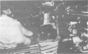
5. Remove the pad from the lifter. There is a slot in the lifter. Use a smaller screwdriver or other blade and a magnetic rod to remove the pad. Note the number on the pad.
1. Adjusting pad
6 Proper pad selection is made as follows:
Chart lookup method:
(Use appropriate chart for exhaust or intake valves, attached to this page, below.)
a. Find number of original (installed) pad number on chart. Read down on chart.
b. Find measured valve clearance (from step 1) on chart. Read across.
c. At the intersection of installed pad number (down) and measured clearance (across) is a new pad number.
I EXAMPLE:
Intake valve, installed pad:
No. 250 (read down) Measured clearance:
0.32 mm (read across) New pad number: No. 270
(intersection of down & across)
NOTE: The new pad number is to be used as a guide only. Verify the correctness of this choice in the following step(s).
7. Install the new pad in the lifter. Install the pad with the number down.
8. Remove tappet adjusting tool,
9. Turn crankshaft to rotate cam several rotations. This will set the pad in the lifter.
10. Check valve clearance (step 3). If clearance is incorrect, repeat preceding steps until proper clearance is obtained.
11. Inspect head cover gasket. If bent or torn, replace gasket.
12. Reinstall removed parts in reverse order.
Alternate shim calculation method:
NOTE:
This is not a Yamaha procedure. This was developed by the XJ Owners' Group.
Since all shims come in .05mm (.002") increments, you can quickly calculate the required size without a chart.
If the measured clearance is within 0.05mm (0.002") of the required clearance, then no change is needed.
If the measured clearance greater than 0.05mm (0.002") but 0.10mm (0.004") or less different than the required clearance then the next size shim is required.
If the measured clearance greater than 0.10mm (0.004") but 0.15mm (0.006") or less different than the required clearance then the next size shim is required.
Clearances that are too small require thinner shims. Clearances that are too large require thicker shims.
Example: Required exhaust valve clearance is 0.16~0.20mm. Measured clearance is 0.12mm (gap too small). Installed shim is Y270. Required shim is one size thinner: Y265.
B. Spark plug
1. Check the electrode condition and wear, insulator color, and electrode gap,
2. Use a wire gauge for measuring the plug gap.
3. If the electrodes become too worn, replace the spark plug.
4. When installing the plug, always clean the gasket surface. Wipe off any grime that might be present on the surface of the spark plug, and torque the spark plug properly.
Standard spark plug:
BPR8ES(NGK) or W24EPR-U (ND) Spark plug gap:
0.7 ~ 0.8 mm (0.028-0.032 in) Spark plug tightening torque:
2.0 m-kg, (14.5 ft-lb)
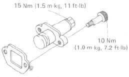
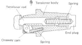
C. Cam chain tensioner
This model has been equipped the automatic cam chain tensioner. No adjustment is necessary.
When installing this tensioner onto the cylinder, proceed as follows:
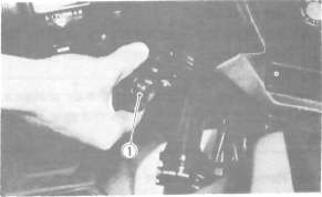
1. Remove the end plug and spring from the tensioner assembly.
2. Unlock the one-way cam by pushing it with your finger and push the tensioner rod into the tensioner body until it stops.
3. Install the tensioner to the cylinder and torque the bolts to the specification.
Tightening torque:
10 Nm (1.0 m-kg, 7.2 ft-lb)
4. Reinstall the spring and end plug with the gasket. Torque the end plug to the specification.
Tightening torque:
15 Nm (1.5 m-kg, 11 ft-lb)
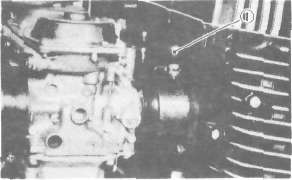
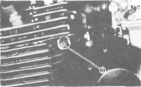
D, Ignition timing 1. Ignition timing is checked with a timing light by observing the position of the stationary pointer and the marks stamped on the timing plate.
The timing plate is marked as follows:
 .... Firing range for No. 1 (L.H.) cylinder
 ... Top Dead Center for No. 1 (L.H.>andNo.4(R.H.) cylinders
2. Connect the timing light to No. 1 (L.H.) spark plug lead wire.
3. Start the engine and keep the engine speed as specified. Use a tachometer to check the engine speed.
Specified engine speed: 1,050 r/min
4. The stationary pointer should be within the limits of " U " on the timing plate. If it exceeds the limits or does not steady, check the timing plate for tightness and/or ignition system for damage. (See "ELECTRICAL")
CAUTION
Never bend the stationary pointer.
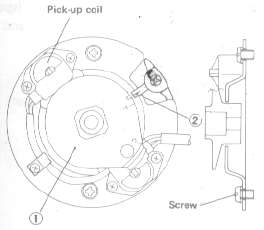
1, Timing plate 2. Stationary pointer
E. Air filter
1. Removal
a. Remove the seat.
b. Remove the fuse box.
1. Fuse box
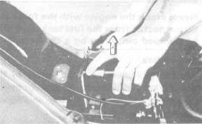
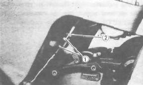
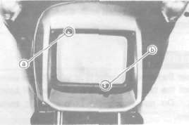
c. Remove the air filter case securing screw. Then, pull the air filter case holding plate backward.
1. Securing screw 2. Holding plate
d. Pull out the air filter case.
e. Pull out the element.
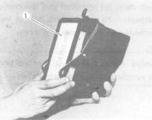
1. Air filter element
2. Cleaning method
Tap the element lightly to remove most of the dust and dirt; then blow out the remaining dirt with compressed air from the inner surface of the element. If element is damaged, replace it.
3. Reassemble by reversing the removal procedure. Check whether the element is seated completely against the case.
4. The air filter element should be cleaned at the specified intervals.
CAUTION:
The engine should never be run without the air cleaner element installed; excessive piston and/or cylinder wear may result.
F. Carburetor
Never crank the engine with the fuel lines disconnected from the fuel tank. Fuel will be pumped out, creating a fjre hazard.
Idle mixture
The idle mixture is set at the factory by the use of special equipment. No attempt should be made by the dealer to change this adjustment.
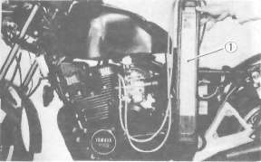
Synchronization
The seat must be removed and the rear of the tank elevated to gain access to the vacuum connections and synchronizing screw.
NOTE:
The valve clearances must be set properly before synchronizing the carburetors.
1. Remove the vacuum pipe from the carburetor manifold (No. 3 cylinder) and turn the fuel cock to "PRI."
2. Remove the rubber caps from the No. 1, 2, and 4 carburetor manifolds.
1. Rubber cap
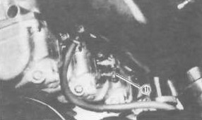
3. Remove either the left or right (but not both) blind plug at the end of the YICS (Yamaha Induction Control System) passage in the cylinder.
1. Blind plug
4. Insert the YICS shut-off tool (special tool P/No. 90890-04068) fully and flip the locking lever.
1. Shut-off tool rubber (P/No 90890-04073)
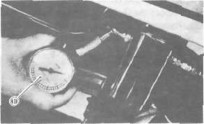
5. Connect each vacuum gauge hose to its proper carburetor.
1. Vacuum gauge
6. Start the engine and allow it to warm up for a few minutes. The warm-up is complete when the engine responds normally to the throttle opening.
7. Make sore the engine idle speed is 950 ~ 1,000 r/min. If it is not, adjust the idle speed with the throttle stop screw.
NOTE:
With the YICS shut off tool fitted, the engine speed generally drops a little. Thus, continue with the following steps at an idle speed of 950-1,000 r/min.
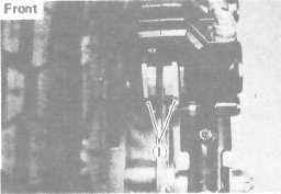
8. Each gauge reading will indicate the same if the carburetors are synchronized. The No. 3 carburetor has no synchronizing screw, and the other carburetors are to be synchronized to it in order, one at a time.
First, synchronize carburetor No. 1 to carburetor No. 2 by turning the No. 1 synchronizing screw until both gauges read the same.
Second, in the same way synchronize carburetor No. 4 to carburetor No. 3. Third, by adjusting No. 2 screw, watch No. 3 carburetor reading. No. 1 and No. 2 carburetors will both change to match No. 3 carburetor.
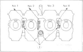
1. Synchronizing screws
9. Remove the YICS shut off tool and reinstall the blind plug.
Tightening torque:
22 Nm (2.2 m-kg, 16 ft-lb)
10. Check the idle speed. Adjust if necessary.
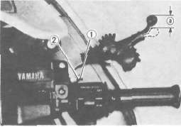
Idle speed adjustment
NOTE
Carburetors must be synchronized before setting the final idle speed. The idle speed adjustment is made by turning only one throttle stop screw.
1. The engine must be warmed up before setting the idle speed.
2. Set the engine idle speed by turning the throttle stop screw in (to increase engine speed) or out (to decrease engine speed).
Standard idle speed: 1,050 ± 50 rpm
1. Throttle stop screw
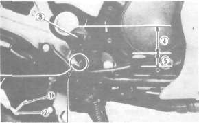
G. Engine oil
1. Oil level measurement
a. Place the motorcycle on its centerstand. Warm up the engine for several minutes.
NOTE:
Be sure the motorcycle is positioned straight up when checking the oil level; a slight tilt toward the side can produce false readings.
b. With the engine stopped, check the oil level through the level window located at the lower part of the light side crank case cover.
NOTE:
Wait a few minutes until the oil level settle before checking.
d. Remove the drain plug and drain the oil.
1. Maximum mark 2. Minimum mark 3. Level window
c. The oil level should be at the maximum level. If the level is lower, add sufficient oil to raise it to the maximum level.
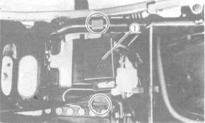
2. Engine oil and oil filter replacement
a. Start the engine and run it a few minutes to warm it up.
b. Place an oil pan under the engine and remove the oil filler cap.
c. Remove the lower panel.
1 Lower panel
1. Drain plug
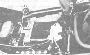
e. Remove the oil filter bolt and filter element.
1. Oil filter cover
f. Reinstall the drain plug (make sure it is tight).
Drain plug torque: 43 Nm (4.2 m-kg, 31.0 ft-lb)
g. Install the new oil filter element, new O-ring and filter cover; tighten the oil filter bolt.
Oil filter bolt torque:
15 Nm (1.5 m-kg, 11.0 ft-lb)
NOTE:
Make sure the O-ring is positioned properly.
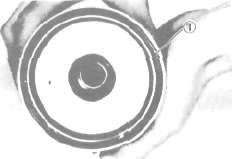
1 - Proper O-ring position
h. Add oil through the oil filler hole.
Periodic oil change:
2.5 L (2.2 Imp. qt. , 2.6US qt.) With oil filter replacement:
2.9 L (2.6 Imp qt, 3.1 US qt.) Recommended oil:
YAMALUBE 4-cycle oil or SAE
20W40 type SE motor oil
CAUTION:
Take care not to allow foreign material to enter the crankcase.
i. After replacing engine oil, and/or the oil filter, be sure to check for oil leakage. The oil indicator light should go off after oil is filled.
CAUTION:
If the indicator light flickers or remains on, the oil level switch may be damaged. Refer to ELECTRICAL for corrective action.
j. Reinstall the lower panel.
H. Final gear oil
1. Oil level measurement
a. Place the motorcycle on a level place and place it on the centerstand. The engine should be cool (at atmospheric temperature).
b. Remove the oil filler cap and check the oil level whether it is to the hole brim. If it is not up to this level, replenish oil.
CAUTION:
Take care not to allow foreign material to enter the final gear case.
1. Final gear oil 2. Correct oil Level
2. Gear oil replacement
a. Place an oil pan under the final gear case.
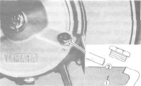
b. Remove the final gear oil filler cap and the drain plug, and drain the oil.
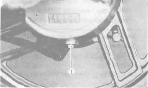
1. Final gear drain plug
WARNING:
When draining or filling, take care not to allow foreign material to enter the final gear case. Do not allow the gear oil to contact the tire and wheel.
c. Reinstall and tighten the final drain plug.
Tightening torque: 23 Nm (2.3 m-kg, 17ft-lb)
d. Fill the gear case to the specified level.
Oil capacity: Final gear case: 0.2 L (0.18 Imp. qt. , 0.21 US qt.)
Recommended oil: SAE 80 API "GL-4" Hypoid gear oil. If desired, an SAE 80W90 hypoid gear oil may be used for all conditions.
e. Reinstall the filler cap securely.
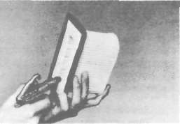
I. Compression pressure measurement
Insufficient compression pressure will result in performance loss and may indicate leaking valves or worn or damaged piston rings.
Procedure:
1. Make sure the valve clearance is correct.
2. Remove the headlight fuse from the fuse box.
3. Warm up the engine 2 ~ 3 minutes. Stop the engine.
4. Remove the all spark plugs.
5. Install a compression-check gauge.
6. Turn over the engine with the electric starter (make sure the battery is fully charged) with the battery is fully charged) with the throttle wide open until the pressure indicated on the gauge does not increase further.
Compression pressure (at sea level):
Standard 834 kPa (8.5 kg/cm2, 121 psi)
Minimum 686 kPa (7 kg/cm2, 100 psi)
Maximum 981 kPa (10 kg/cm2, 142 psi)
When cranking the engine, ground the removal spark plug wires to prevent sparking.
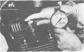
1. Compression gauge
7. If the pressure is too low, squirt a few drops of oil into the cylinder being measured. Measure compression again. If there is a higher reading than before (without oil), the piston rings may be worn or damaged. If the pressure remains the same after measuring with the oil, either or both the rings and valves may be the cause.
8. Check each cylinder. Compression pressure should not vary more than the specified value from one cylinder another.
Difference in gauge reading: Less than 98.1 kPa (1.0 kg/cm2, 14 psi)
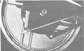
J. Clutch adjustment
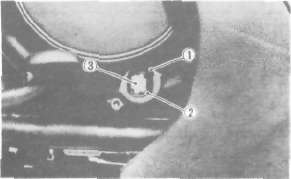
Free play adjustment
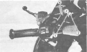
1. Locknut 2. Adjuster. 2—3 mm (0.08—0.12 in)
a. Loosen either the handle lever adjuster lockout or the cable length-adjuster lock-nut.
1 Locknut 2. Adjuster
b. Turn the cable length-adjuster either in or out until the proper lever free play is achieved.
Chassis Maintenance
Chassis MaintenanceCHASSIS
A. Fuel petcock
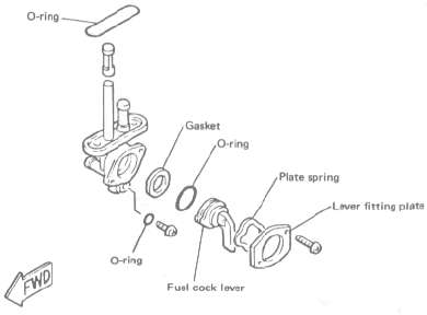
If the fuel petcock is leaking or excessively contaminated, it should be removed from the fuel tank and inspected.
1. Remove the fuel tank, and position it so that fuel wilt not spill when the petcock is removed.
2. Remove the petcock and inspect the filter screen. Replace the filter if srious-ly contaminated.
3. Remove the screws on the front and rear of the petcock and remove the plate, gaskets, lever, and diaphragm.
4. Inspect all components and replace any that are damaged. If the diaphragm is in any way damaged, or the petcock body gasket surfaces scratched or corroded, the petcock assembly must be replaced. If there is abrasive damage to any component, the fuel tank must be drained and flushed.
5. Reassemble the petcock and install it on the fuel tank.
B. Front and rear brake
1. Brake adjustment
a. Front brake lever free play adjustment. The brake can be adjusted by simply adjusting the free play of the brake lever. The piston in the caliper moves forward as the brake pad wears out, automatically adjusting the clearance between the brake pads and brake disc.
CAUTION:
Proper lever free play is essential to avoid excessive brake drag.
1. Adjuster 2. Lock nut a. 5 - 8 mm (0.2 - 0.3 in)
1) Loosen the adjuster locknut on the brake lever.
2) Turn the adjuster so that the brake lever movement at the lever end is 5- 8 mm (0.2-0.3 in) before the adjuster contacts the master cylinder piston.
3) After adjusting, tighten the locknut. b. Rear brake pedal height adjustment
1) Loosen the adjuster locknut {for pedal height).
2) By turning the adjuster bolt clockwise or counterclockwise, adjust the brake pedal position so that its top end is approximately 20 mm {0.78 in) below the footrest top end.
3) Secure the adjuster locknut.
WARNING:
After adjusting the pedal height, the brake pedal free play should be adjusted.
1. Adjuster bolt (for pedal height) 2. Locknut 3. Footrest
4. Pedal height 40 mm (1.6 In) 5. Free play 20 30 mm (0.8 - 1.2 in)
c. Rear brake pedal free play adjustment Turn the adjuster on the brake rod clockwise or counterclockwise to provide the brake pedal with a free play of 20~30 mm {0.8-1.2 in).
1. Adjuster
WARNING:
Check the operation of the brake light after adjusting the rear brake.
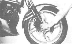
2. Front brake pad and rear brake shoe check
a. Front brake pad
To check, look at the pad in front. If any pad is worn to the wear limit, replace both pads in the caliper.
1. Wear indicator
b. Rear brake shoe
To check, see the wear indicator position while depressing the brake pedal. If the indicator reaches to the wear limit line, replace the shoes.
1. Wear limit 2. Wear indicator
3. Brake fluid
Insufficient brake fluid may allow air to enter the brake system, possibly causing the brake to become ineffective. Check the brake fluid level and replenish when necessary, observing these precautions:
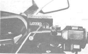
1. Lower level
a. Use only the designated quality brake fluid; otherwise, the rubber seals may deteriorate, causing leakage and poor brake performance.
Recommended brake fluid: DOT# 3
b. Refill with the same type and brand of brake fluid; mixing fluids may result in a harmful chemical reaction and lead to poor performance.
c. Be careful that water or other contamination does not enter the master cylinder when refilling. Water will significantly lower the boiling point and may result in vapor lock.
d. Brake fluid may erode painted surfaces or plastic parts. Always clean up spilled fluid immediately.
e. Check the cause if the brake fluid level goes down.
Brake fluid replacement
1. Complete fluid replacement should be done only by trained Yamaha service personnel or other qualified mechanic.
2. Complete fluid replacement should be done whenever the caliper cylinder or master cylinder is disassembled, or the fluid becomes seriously contaminated.
3. Replace the following components whenever damaged or leaking, also:
a. Replace all brake seals every two years.
b. Replace all brake hoses every four years.
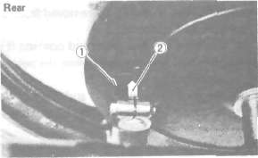
Brake light switch adjustment
The brake light switch is operated by the movement of the brake pedal. To adjust, hold the switch body with the hand so it does not rotate and turn the adjusting nut. Proper adjustment is achieved when the brake light comes on slightly before the brake begins to take effect.
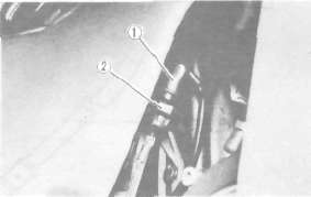
1. Switch body 2. Adjusting nut
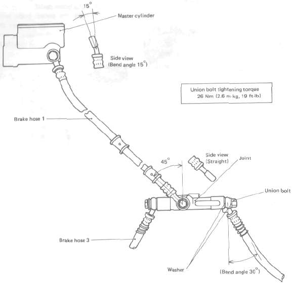
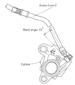
Front brake hose installation
The front brake hoses should be installed as shown in the illustration.
NOTE:
1. When installing the brake hose to the master cylinder, the joint, or the caliper, pay attention to the banjo fitting angle; see the illustration.
2. When installing the banjo fitting to the caliper or the joint, use the stopper.
3. When installing the banjo fitting to the master cylinder, brake hose 1 should not have any excessive twists or bends in it, nor should it be tightly stretched.
FRONT BRAKE HOSE INSTALLATION
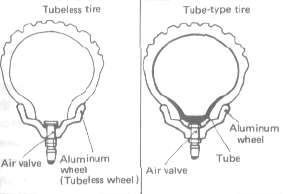
C. TubeIess tires and aluminum wheels
This motorcycle is equipped with aluminum wheels designed to be compatible with either tube or tubeless tires. Tubeless tires are installed as standard equipment.
WARNING:
Do not attempt to use tubeless tires on a wheel designed for use only with tube-type tires. Tire failure and personal injury may result from sudden deflation.
Tube-type Wheel -> Tube-type tires only
Tubeless type Wheel -> Tube-type or Tubeless tires
When using tube-type tires, be sure to install the proper tube also.
To insure maximum performance, long service, and safe operation, note the following precautions.
1. Check tire pressure before riding; adjust as necessary.
2. Before operation, always check the tire surfaces for wear and/or damage; look for cracks, glass, nails, metal fragments, stones, etc. Correct any such hazard before riding.
3. Always inspect the aluminum wheels before a ride. Place the motorcycle on its centerstand and check for cracks, bends, or warpage of the wheels. Do not attempt even small repairs to the wheel. If a wheel is deformed or cracked, it must be replaced.
4. Tires and wheels should be balanced whenever either one is changed or replaced. Failure to have a wheel assembly balanced can result in poor performance, adverse handling characteristics, and shortened tire life.
5. After installing a tire, ride conservatively to allow the tire to seat itself on the rim properly. Failure to allow proper seating may cause tire failure, resulting in damage to the motorcycle and injury to the rider.
6. After repairing or replacing a tire, check to be sure the valve stem locknut is securely fastened. If not, torque it as specified.
Tightening torque: 0.15 m-kg (1.1 ft-lb)
D. Front fork oil change
NOTE:
It is recommended that you proceed to the front fork oil change after clearing the front fork area of the fairing. This makes the work easier without the fairing being damaged.
WARNING:
1. Fork oil leakage cause loss of stability and safe handling. Oil can contaminate front brakes causing loss of braking power. Have any problem corrected before operating the motorcycle.
2. Securely support the motorcycle so there is no danger of it falling over.
1, Raise the motorcycle or remove the front wheel so that there is no weight on the front end of the motorcycle.
2. Remove the handlebar cover and handlebars.
3. Remove the air valve cap from the left fork.
1, Air valve cap
4. Keep the valve open while pressing it for several seconds so that the air can be let out of the inner tube.
l.Push
5. Remove the rubber cap from the top of each fork.
6. Loosen the pinch bolts and remove the cap bolt from each inner tube.
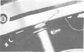
1. Cap bolt 2 Pinch bolt
7. Place an open container under each drain hole. Remove the drain screw from each outer tube.
WARNING:
Do not allow oil to contact the disc brake components. If any oil should contact the brake components, it must be removed before the motorcycle is operated. Oil will cause diminished braking capacity and will damage the rubber components of the brake assembly.
1. Drain screw
8. When most of the oil has drained, slowly raise and lower the outer tubes to pump out the remaining oil.
9. Inspect the drain screw gasket. Replace if damaged. Reinstall the drain screw.
10. Pour the specified amount of oil into the fork inner tube.
Front fork oil (each fork): 238 cm3 (8.4 Imp oz, 8.0 US oz) Yamaha Fork Oil 10wt or equivalent
11. After filling, slowly pump the outer tubes up and down to distribute the oil.
12. Inspect the 0-ring on the cap bolt.
13. Reinstall the cap bolt and the rubber cap. Then, tighten the pinch bolts.
Tightening torque:
Cap bolt: 20 Nm (2.0 m-kg, 14.0 ft-lb)
Pinch bolt: 17 Nm (1.7 m-kg, 12.0 ft-lb)
14. Fill the fork with air using a manual air pump or other pressurized air supply. Refer to "Front fork and rear shock absorber adjustment" for proper air pressure adjusting.
Maximum air pressure: 118 kPa (1.2 kg/cm2, 17 psi)
Do not exceed this amount.
15. Reinstall the air valve cap to the left fork.
16. Reinstall the handlebars and handlebar cover.
NOTE:
First tighten the bolts on the front side of the handlebar holder, and then tighten the bolts on the rear side.
Handlebar upper holder tightening torque: 19 Nm (1.9 m-kg, 13.0 ft-lb)
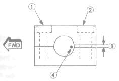
1.1st 2. 2nd 3. Gap 4. Punch mark
Front fork and rear shock adjustment
CAUTION:
Don't dent the air chamber nor damage the air hose. It will result in an air leakage.
Front fork:
NOTE:
Since the right and left front forks are connected by air hose, there is only one valve where the air pressure is measured and adjusted.
1. Air pressure
a. Elevate the front wheel by placing the motorcycle on the centerstand.
NOTE:
When checking and adjusting the air pressure, there should be no weight on the front end of the motorcycle.
b. Remove the air valve cap.
c. Using the air check gauge, check and adjusted the air pressure. If the air pressure is increased, the suspension becomes stiffer and if decreased, it becomes softer.
To increase: Use a manual air pump or other pressurized air supply.
To decrease: Release the air by pushing the valve pin.
1. Air check gauge
NOTE:
An optional air check gauge is available. P/No. 2X4-2811A-00
Standard air pressure: 39.2 kPa (0.4 kg/cm3, 5.7 psi)
Maximum air pressure: 118 kPa (1.2 kg/cm2, 17 psi)
Minimum air pressure: 39.2 kPa (0.4 kg/cm2, 5.7 psi)
CAUTION:
Never exceed the maximum pressure or oil seal damage may occur.
WARNING:
Never pressurize the front fork above the maximum or below the minimum air pressure. It will cause damage to front fork and/or loss Of motorcycle control.
d. Reinstall the air valve cap.
E. Rear shock absorber
NOTE:
Since the right and left shock absorbers are connected by air hose, there is only one valve where the air pressure is measured and adjusted.
1. Air pressure
a. Elevated the rear wheel by placing the motorcycle on the centerstand.
NOTE:
When checking and adjusting the air pressure, there should be no weight on the rear end of the motorcycle.
b. Remove the air valve cap.
c. Using the air check gauge, check and adjust the air pressure. If the air pressure is increased, the suspension becomes stiffer, and if decreased, it becomes softer,
To increase: Use a manual air pump or other pressurized air supply,
To decrease. Release the air by pushing the valve pin.
1. Air check gauge
NOTE: An optional air check gauge is available. P/No. 2X4-2811A-00
Standard air pressure: 98.1 kPa (1.0 kg/cm2, 14 psi)
Maximum air pressure: 392 kPa (4.0 kg/cm2, 57 psi)
Minimum air pressure: 98.1 kPa (1.0 kg/cm2, 14 psi)
CAUTION:
Never exceed the maximum pressure or oil seal damage may occur.
WARNING:
Never pressurize the shock absorber above the maximum or below the minimum air pressure. It will cause damage to rear shock absorber and/or loss of motorcycle control.
d. Reinstall the air valve cap.
2. Damping
a. Turning the damping adjuster to increase or decrease the damping.
b. If the damping adjuster is turned toward the "4", the damping becomes harder; if the adjuster is turned toward the "1", damping becomes softer.
Standard position - No. 1
No. 1 - Minimum damping
No. 4 — Maximum damping
1. Damping adjuster
Always the shock absorbers on each side to the same position. Uneven adjustment will cause an improper riding position.
F. Steering head adjustment
The steering assembly should be checked periodically for looseness.
1. Raise the front end of the motorcycle so that there is no weight on the front wheel.
2. Grasp the bottom of the forks and gently rock the fork assembly backward and forward, checking for looseness in the steering assembly bearings.
3. If there is looseness in the steering head, loosen the steering stem and front fork pinch bolts and steering fitting bolt.
4. Use a steering nut wrench to loosen top steering fitting nut. The top nut serves as a locknut.
5. Tighten the lower steering fitting nut until the steering head is tight, but does not bind when forks are turned.
6. Retighten the top steering fitting nut, steering fitting bolt and steering stem and front fork pinch bolts, in that order.
7. Recheck steering adjustment to make sure there is no binding when the forks are moved from lock to lock. If necessary, repeat adjustment procedure.
G. Cable inspection and lubrication
Warning:
Damage to the outer housing of the various cables may cause corrosion; free movement could be obstructed. An unsafe condition may result, so replace such cables as soon as possible.
1. If the inner cables do not operate smoothly, lubricate or replace them.
Recommended lubricant:
Yamaha Chain and Cable Lube or SAE 10W30 motor oil
H. Throttle cable and grip lubrication The throttle twist grip assembly should be greased when the cable is lubricated, since the grip must be removed to get at the end of the throttle cable. Two screws clamp the throttle housing to the handlebar. Once these two are removed, the end of the cable can be held high to pour in several drops of lubricant. With the throttle grip disassembled, coat the metal surface of the grip assembly with a suitable all-purpose grease to cut down friction.
I. Rear arm pivot bearings The swingarm must pivot freely on its bearings but not have any excess play. Check and adjust pivot bearings if necessary.
J. Brake and change pedals/brake and clutch levers Lubricate the pivoting parts of each lever and pedal.
Recommended lubricant:
Yamaha Chain and Cable Lube or SAE 10W30 motor oil
K. Centerstand and sidestand pivots Lubricate the centerstand and sidestand at their pivot points.
Recommended lubricants:
Yamaha Chain and Cable Lube or SAE 10W30 motor oil
Electrical Maintenance
Electrical MaintenanceELECTRICAL
A. Battery
1. The fluid level should be between the upper and lower level marks. Use only distilled water if refilling is necessary.
CAUTION: Normal tap water contains minerals which are harmful to a battery; therefore, refill only with distilled water.
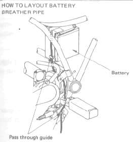
2. Always make sure the connections are correct when installing the battery. Make sure the breather pipe is properly connected, properly routed, and is not damaged or obstructed.
CAUTION: The battery must be charged before using to insure maximum performance. Failure to properly charge the battery before first use or a low electrolyte level will cause premature failure of the battery.
Charging current: 1.2 amps/10 hrs or until the specific gravity reaches 1.280 at 20°C (6°F)
WARNING: Battery electrolyte is poisonous and dangerous, causing severe burns, etc. It contains sulfuric acid. Avoid contact with skin, eyes, or clothing.
Antidote:
EXTERNAL-Flush with water,
INTERNAL -Drink large quantities of water or milk. Follow with milk of magnesia, beaten egg, or vegetable oil. Call physician immediately.
Eyes. Flush with water for 15 minutes and get prompt medical attention.
Batteries produce explosive gases. Keep sparks, flame, cigarettes, etc. away. Ventilate when charging or using in closed space. Always shield eyes when working near batteries. KEEP OUT OF REACH OF CHILDREN.
Replenishing the battery fluid
A poorly maintained battery will deteriorate quickly. The battery fluid should be checked at least once a month.
1. Remove the seat.
2. Remove the handlebar cover and side panels (left and right).
3. The level should be between the upper and lower level marks. Use only distilled water if refilling is necessary.
CAUTION: Normal tap water contains minerals which are harmful to a battery; therefore, refill only with distilled water.
CAUTION: Install the battery sensor into 3RD hole from positive terminal.
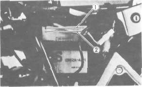
1. Upper level 2. Lower level
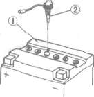
1. Battery 2. Battery sensor
4. When the motorcycle is not to be used for a month or longer, remove the battery and store it in a cool, dark place. Completely recharge the battery before reusing.
5. If the battery is to be stored for a longer period than the above, check the specific gravity of the fluid at least once a month and recharge the battery when it is too low.
6. Always make sure the connections are correct when putting the battery back in the motorcycle.
Make sure the breather pipe is properly connected and is not damaged or obstructed.
CAUTION: Make sure that the connection to the battery is correct; otherwise, damage to the microcomputer may occur.
7. Reinstall the side panels (left and right) and handlebar cover. Then, reinstall the seat.
B. Headlight
This motorcycle is equipped with a quartz bulb headlight. If the headlight bulb burns out, replace the bulb as follows:
1. Headlight bulb replacement
a. Remove the headlight nacelle.
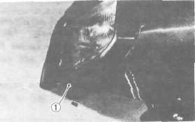
1. Nacelle holding screw
b. Remove the two blind plugs from the upper panels (left and right).
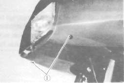
1. Blind plug
c. Remove the 2 screws holding the light unit assembly to the headlight body.
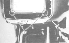
1. Holding screw
d. Disconnect the leads and remove the light unit assembly.
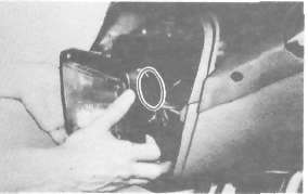
e. Turn the bulb holder counterclockwise and remove the defective bulb.
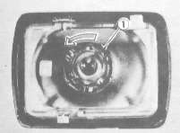
1. Bulb holder
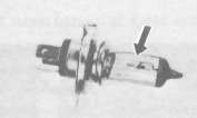
f. Slip a new bulb into position and secure it with the bulb holder.
CAUTION: Avoid touching the glass part of the bulb. Also keep it free from oil stains; otherwise, the transparency of the glass, life of the bulb, and luminous flux will be adversely affected. If the glass is oil stained, thoroughly clean it with a cloth moistened with alcohol or lacquer thinner.
WARNING: Keep flammable products or your hands away from the bulb while it is on, because it heats up. Do not touch the bulb until it cools down.
g. For reassembly, follow procedure below with care.
1 ( Install the two blind plugs.
2) Make sure the projecting portions of the headlight nacelle are positioned correctly.
3) Adjust the headlight beam if necessary.
2. Headlight beam adjustment:
a Horizontal adjustment:
To adjust the beam to the left, turn the adjusting screw clockwise.
To adjust the beam to the right, turn the screw counterclockwise.
b. Vertical adjustment:
To adjust the beam to the upper, turn the adjusting screw clockwise.
a. Horizontal adjusting screw b Vertical adjusting screw
C. Fuse
1. The fuse block is located under the seat.
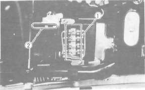
1. Fuse 2. Spare fuse
2. If any fuse is blown, turn off the ignition switch and the switch in the circuit in question, install a new fuse of proper amperage.
Turn on the switches, and see if the electrical device operates. If the fuse immediately blows again, find the cause in the circuit in question.
WARNING: Do not use fuses of a higher amperage rating than those recommended. Substitution of a fuse of improper rating can cause extensive electrical system damage and possible fire.