Chapter 8, Appendices
Chapter 8, AppendicesSpecifications
SpecificationsGeneral Specifications
General SpecificationsI. GENERAL SPECIFICATIONS
|
1. |
Model Code Number |
16G |
|
2. |
Federal V.I.N. Number |
JYA16G00 "CA000101 |
|
3. |
Frame Starting Number |
16G 000101 |
|
4. |
Engine Starting Number |
16G-000101 |
|
5. |
Dimensions: |
2,170 mm (85.4 in) |
|
6. |
Weight: |
249 kg (549 lb) |
|
7. |
Minimum Turning Radius |
2,600 mm (102.4 in) |
|
8. |
Engine: |
D.O.H.C., air-cooled, gasoline |
|
9. |
Lubrication System |
Pressure lubricated. Wet sump |
|
10- |
Engine Oil Type or Grade |
Yamalube 4-cycle oil, SAE 20W40 type SE motor oil |
|
11. |
Engine Oil Capacity |
2.5 L (2.20 Imp qt, 2.64 US qt) |
|
12. |
Middle/Final Gear Oil |
SAE 80 API "GL-4" Hypoid gear oil |
|
13. |
Air Filter |
Dry type element |
|
14. |
Fuel Type |
Premium gasoline (Research octane of 95 or more) |
|
15. |
Carburetor |
BS30 |
|
16. |
Spark Plug |
BP8ES. W24EP-U |
|
17. |
Clutch |
Wet. multiple disc |
|
18.
e.
|
Transmission: |
Gear Spur gear. 49/36 (1.361) Bevel gear. 19/18(1.055) Bevel gear. 32/11 (2.909) 35/16(2.187) |
|
19. |
Chassis: |
Tubular steel double cradle |
|
20. |
Tires |
Tubeless |
| 21.
a. b. c.
|
Tire Pressure UP to 90 kg (198 lb| load* (F) (R) 90 kg (198 lb) -166 kg (366 lb) load* (F) (R) Highspeed Riding (F) (R) *Total weight of accessories, etc. excepting motorcycle. |
(Cold pressure)
177 kPa (1.8 kg/cm2. 26 psi) 226 kPa (2.3 kg/cm2 33 psi) 196 kPa (2.0 kg/cm2. 28 psi)
|
|
22. |
Brake |
Dual hydraulic disc Right hand Drum brake Right foot |
| 23. a. b. |
Suspension Front Suspension Rear Suspension |
Telescopic fork |
| 24. a. b. |
Shock Absorber Front Shock Absorber Rear Shock Absorber |
Oil damper, air and coil spring |
| 25. a. b. |
Wheel Travel Front Wheel Travel Rear Wheel Travel |
140 mm (5.6 in) |
| 26 a. b. c, d. |
Electrical. Ignition System Generator System Battery Type or Model Battery Capacity |
Battery ignition {Full transistor ignition) |
|
27. |
Headlight Type |
HALOGEN (Anti-vibratory bulb) |
| 28. a. b. c. d. e. |
Bulb Wattage x Pcs Headlight Turn light Tail/Brake light Meter light License light |
60W/55W 1 pcs. |
| 29. a. b. c. d. |
Indicator light Wattage x Pcs. Neutral High Beam Warning > Turn |
3.4W x 1 pcs. |
Maintenance Specifications -- Engine
Maintenance Specifications -- EngineA, Engine
|
1 |
Cylinder head |
22.7 cc
|
||
| 2. a. b. c. d. |
Cylinder Material Bore Size Taper Limit Out-of-round Limit |
Aluminum alloy with cast iron sleeve |
||
| 3. a. b. c. d. |
Camshaft Drive Method Cam Cap Inside Diameter Camshaft Outside Diameter Shaft-to-cap Clearance |
Chain drive Center 25+0.021-0 mm (0.98+0.0008-0 in) 25-0.020-0.33 mm (0.98-0.0008-0.0013 in) 0.020 ~ 0.054 mm (0.0008 - 0.0021 in) |
||
| e. | 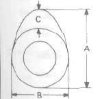 |
Cam Dimensions
Intake Exhaust |
"A" "B" "C" "A" |
35.50 mm (1.398 in) 28.00 mm (1.102 in) 7.50 mm (0.295 in) 35.50 mm (1.398 in) |
| f. | 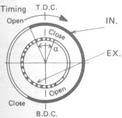 |
Valve Timing Intake: Open Close Exhaust: Open Close Over Lap |
B.T.D.C. 28° B.B.D.C. 53° 51° |
|
| 9. | 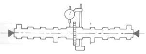 |
Camshaft Runout Limit | 0.06 mm (0.0024 in) |
|
| h. i. |
Cam Chain Type/Number of Links Cam Chain Adjustment Method |
BUSH-CHAIN/120 Automatic |
||
| 4. | Valve, Valve Seal, Valve Guide | ||||
|
a. |
Valve Clearance (Cold) IN.
|
0.11 *- 0.15 mm (0.0043 - 0.0059 in) 0.16 - 0.20 mm (0.0063 -0.0079 in) |
|||
|
b. |
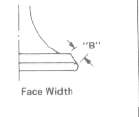
Valve Dimensions |
|
|||
|
|
|
|
|||
|
"A" Head Dia. |
33 ± 0.1 mm (1.30 ± 0.0039 in) |
||||
|
"B" Face Width |
2 3 mm (0.091 in) |
||||
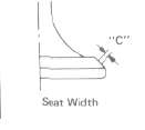
| "C" Seat Limit Width IN. EX. |
1 ± 0.1 mm (0.0394 ± 0.039 in) 1 ± 0.1 mm (0.0394 i 0 039 in) |
||||
|
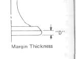
"D' Margin Thickness Limit |
0.7 mm (0.028 in) 0.7 mm (0.028 in) |
||||
|
c. |
Stem Outside Diameter |
7-0.10-0.025mm (0.2756 -0.0004-0.0010 in) |
|||
|
d |
Guide Inside Diameter |
7+0.12-0. mm (0.2756 -0.0005-0. in) |
|||
|
e. |
Stem-to guide Clearance |
0.010- 0.037 mm (0.004- 0.0015 in) |
|||
|
f. |
Stem Runout Limit |
 |
<0.03mm (0.0012 in) > |
||
|
g- |
Valve Seat Width |
1.0 mm (0.039 in) |
|||
|
6. Valve Spring |
|||||
|
a. |
Free Length |
35.9 mm (1.413 in) 39.5 mm (1.555 in) |
|||
| b. | Spring rate Inner Spring IN. EX. Outer Spring IN. EX. |
2.36 kg/mm (132 lb/in) 4.58 kg/mm (256 lb/in) |
|||
| c. | Compression Length (Valve Closed) Inner Spring IN. EX. Outer Spring IN. EX. |
31,0 mm (1.220 in) 31.0 mm (1.220 in) 34,0 mm (1.339 in) |
|||
| d. | Compression Force (Valve Closed) Inner Spring IN. EX. Outer Spring IN. EX. |
9.0 kg (20 lb) 19.1 kg (42.1 lb) |
|||
| e. | Tilt Limit, all springs: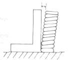 |
2.5° | |||
| f. | Direction of Winding (Top View) | Intake |
Exhaust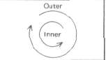 |
||
| 7. | Piston | ||
| a. | Piston Size/ Measuring Point (A) | 63.0 mm (2.48 in)/ 7.5 mm (0.295 in) (From bottom line of piston skirt) 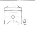 |
|
| b. | Clearance between Piston & Cylinder < Limit > |
0.03 - 0.05 mm (0.0012 -0.0020 in) <0.1 mm (0.0049 in) > |
|
| c. | 0versize 1st 2nd 3rd 4 th |
--- 63.50 mm (2.50 in) --- 64.00 mm (2.52 in) |
|
| d. | Piston Pin Hole Off-Set | 0.5 mm (0.02 in) / lnside | |
|
8. |
Piston Ring |
||
|
a. |
Sectional Sketch |
|
|
|
|
Top Ring |
B = 1.2-0.01-0.03 mm (0.47-0.0004-0.0012 in) |
|
|
|
2nd Ring |
B = 1.5-0.01-0.03 mm (0.59-0.0004-0.0012 in) |
|
|
|
Oil Ring |
B = 2.5mm (0.098 in) |
|
| b. | End Gap (Installed) Limit Top Ring 2nd Ring Oil Ring |
0.15- 0.35 mm (0.0059 - 0.0138 in) < 1.0 mm (0.039 in) > 0.15-0.35 mm (0.0059-0.0138 in) < 1.0 mm (0.039 in) > 0.3-0.9 mm (0.012 ~ 0.035 in) < 1.5 mm (0.059 in) > |
|
| c. | Side Clearance Top Ring Limit 2nd Ring Limit |
0.03-0.07 mm (0.0012- 0.0028 in) <0.15mm (0.0059 in)> 0.02-0.06 mm (0.0008-0.0024 in) <0.15mm (0.0059 in) > |
|
| d | Plating or Coating Top Ring 2nd Ring Oil Ring |
Chrome plated. Ferox coating ---- Chrome plated. Ferox coating |
|
| 9. a. b. |
Connecting Rod Oil Clearance Color Code |
0.03-0.09 mm (0.0012- 0.0035 in) 1. Blue, 2. Black, 3. Brown, 4. Green |
|
| 10. | Crankshaft | 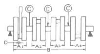 |
|
|
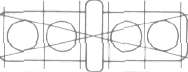
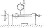
a. |
Crank Width "A" |
A1 = 56.15 mm (2.21 in) |
|
|
b. |
Assembly Width "B" |
341.4 ±0.6 mm (13.44± 0.024 in) |
|
|
c. |
Deflection Limit "C" |
<0.04mm (0.0016 in)> |
|
|
d. |
Big End Side Clearance "D" |
0.16-0.27 mm (0.006-0.011 in) |
|
|
e. |
Journal Oil Clearance |
0.020-0.044 mm (0.0008-0.0017 in) |
|
|
f. |
Color Code _ Corresponding Size |
1.5+0.006+0.002mm(0.0591+0.00024+0.00008in) |
|
|
Black |
1.5+0.002-0.002mm(0.0591+0.00008-0.00008in) |
||
|
Brown |
1.5-0.002-0.006mm(0.0591-0.00008-0.00024in) |
||
|
Green |
1.5-0.006-0.010mm(0.0591-0.00024-0.00039in) |
||
|
Yellow |
1.5-0.010-0.014mm(0.0591-0.00039-0.00055in) |
||


|
11. i. i |
Clutch |
3.0 ±0.1 mm (0.12 ± 0.004 in)/8 pcs. 87-91 27-32 |
|
12. |
Transmission |
<0.08mm (0.0031 in) > |
|
13. |
Shifter |
Cam drum |
|
14. |
Carburetor |
BS30/MIKUNI/4pcs. |
|
15. |
Turbocharger |
TC0306A/MITSUBISHI |
|
16. |
Lubrication System: |
|
|
a.
d. |
Oil Filter Type |
Paper filter 18+0-0.02 mm (0.709+0-0.0008 in) |
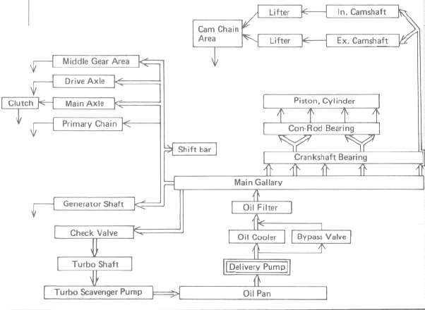
h. Lubrication Diagram
|
17. |
Middle Gear Backlash |
0.1 ~ 0.2 mm (0.0039 - 0.0079 in) |
|
18. |
Final Gear Backlash |
0.1- 0.2 mm (0.0039-0.0079 in) |
|
19. |
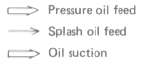
Crankcase Tightening Sequence |
|
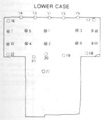
Tightening torque:
 ..... 8 mm bolt: 24 Nm (2.4 m-kg. 17.5 ft-lbl
![]() ..... 6 mm bole 12 Nm (1.2 m-kg, 8.7 ft-lbl
..... 6 mm bole 12 Nm (1.2 m-kg, 8.7 ft-lbl
|
20. Tightening Torque |
|||||||
|
Part to be tightened |
Part name |
Thread size |
Q'ty |
Tightening torque |
Remarks |
||
|
Nm |
m-kg |
1Mb |
|||||
|
ENGINE |
|||||||
|
Cylinder head |
Nut |
M10 P1 .25 |
12 |
36 |
3.6 |
25 |
Apply oil. |
|
Cylinder head cover |
Bolt |
M6 P1.0 |
20 |
1.0 |
1.0 |
7.2 |
|
|
Spark plug |
- |
|
4 |
20 |
2.0 |
14 |
|
|
Cylinder |
Nut |
M8 P1.25 |
2 |
20 |
2.0 |
14 |
Cam chain case Front & Rear |
|
Cylinder holding bolt |
Stud bolt Bolt |
M10P1.25 |
7 |
20 |
2.0 |
14 |
Apply oil |
|
Cam shaft cap |
Bolt |
M6 P1.0 |
20 |
10 |
1.0 |
7.2 |
Tighten in 3-stages. |
|
Cam sprocket |
Bolt |
M7 P1.0 |
4 |
20 |
2.0 |
14 |
|
|
Cam chain tensioner end plug |
|
M11 P1.0 |
1 |
15 |
1.5 |
11 |
|
|
Cam chain tensioner securing bolt |
Bolt |
M6 P1.0 |
2 |
10 |
1.0 |
7.2 |
|
|
Connecting rod |
Nut |
M7 P0.75 |
8 |
25 |
2.5 |
18 |
|
|
Generator (rotor) |
Bolt |
M10 PI .25 |
1 |
55 |
5.5 |
40 |
|
|
Drain plug |
Bolt |
M14 P1.5 |
1 |
43 |
4.3 |
31 |
Crankcase drain |
|
Oil filter |
Bolt |
M20 P1.5 |
1 |
15 |
1.5 |
11 |
|
|
Pump cover |
Screw |
M6 P1.0 |
|
7 |
0.7 |
5.1 |
|
|
Strainer cover |
Bolt |
M6 P1.0 |
13 |
10 |
1.0 |
7.2 |
|
|
Crankcase |
Flange Bolt |
M8 P1.25 |
12 |
24 |
2.4 |
17 |
|
|
Clutch boss |
Nut |
M20 P1.0 |
1 |
72 |
7.2 |
52 |
|
|
Clutch spring screw |
Bolt |
M6 P1.0 |
5 |
10 |
1.0 |
7.2 |
|
|
Change Pedal |
Bolt |
M6 P1.0 |
1 |
10 |
1.0 |
7.2 |
|
|
Neutral Switch |
- |
M10 P1.25 |
1 |
20 |
2.0 |
14 |
|
|
Exhaust Pipe |
Nut |
M6 P1.0 |
8 |
10 |
1.0 |
7.2 |
|
|
Oil cooler |
Joint Nut |
M22 PI.5 |
2 |
45 |
4.5 |
32 |
|
|
SHAFT DRIVE: |
|||||||
|
- Middle Gear - |
|||||||
|
Drive Shalt |
Nut |
M34 PI .5 |
1 |
110 |
11 |
80 |
Stake. |
|
Mount cover |
Screw |
M8 PI.25 |
4 |
25 |
2.5 |
18 |
Stake. |
|
Driven shaft |
Nut |
M14 Pl.5 |
1 |
120 |
12 |
85 |
Use LOCTITE: Stake |
|
Bearing cap |
Flange Bolt |
M8 P1.25 |
4 |
25 |
2.5 |
18 |
|
|
- Final Gear- |
|||||||
|
Drive Shaft |
Nut |
M14 P1.5 |
1 |
110 |
11 |
80 |
|
|
Bearing housing |
Flange Bolt |
M10 P1.25 |
2 |
23 |
2.3 |
17 |
|
|
Bearing housing |
Nut |
M8 P1.25 |
6 |
23 |
2.3 |
17 |
|
|
Oil mount screw |
Plug |
M14 P1.5 |
1 |
23 |
2.3 |
17 |
|
|
Oil drain screw |
Plug |
M14 P1.5 |
1 |
23 |
2.3 |
17 |
|
|
Bearing retainer |
|
M65 P1.5 |
1 |
110 |
11 |
80 |
Left hand screw |
Maintenance Specifications -- Chassis
Maintenance Specifications -- ChassisHTML clipboard
B. Chassis
|
1. c. |
Steering System |
Ball Bearing 19 pcs/ 1/4 in |
|
2.
d. f. |
Front Suspension Oil Grade |
140 mm (5.51 in) 4.13 N/mm (0.421 kg/mm. 23.6 lb/in) / 0~100 mm (0-3.94 in) 180 mm (7.09 in) |
|
3. d. |
Rear Suspension |
80 mm (3.15 in) |
|
4. |
Rear Arm |
0 mm (0 in) |
|
5. |
Wheel |
Cast Wheel <0.5mm (0.02 in)> |
|
|
|
|
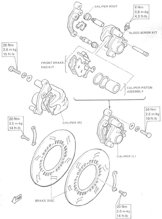
| 6-1. a. b. |
Disc Brake Type Front Outside Dia. x Thickness Front |
Dual disc
267 x5 mm (10.5x0.2 in) |
|
|
c. |
|
Pad Thickness < Limit > |
6.8 mm {0.27 in) |
|
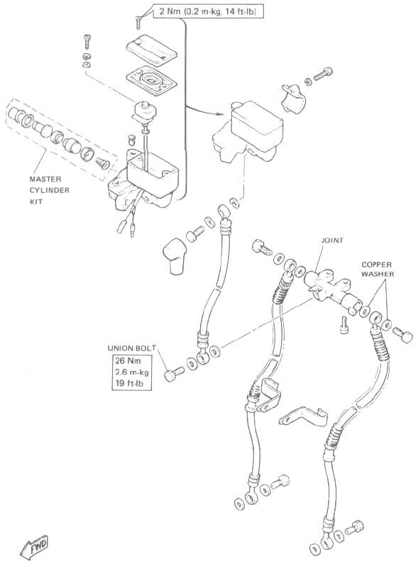
d. |
Master Cylinder Inside Dia. |
15.87 mm (0.62 in) |
|
|
6.2. |
Drum Brake |
Leading trailing 200 mm (7.87 in) 68 mm (2.68 in) |
|
|
7. |
Brake Lever & Brake Pedal |
5.0-8.0 mm (0.2-0.3 in) |
|
|
8. |
Clutch Lever Free Play |
2- 3 mm (0.08-0.12 in) |
|

Tightening torque
|
Part to be tightened |
Part name |
Thread size |
Q'ty |
Tightening |
Remarks |
|
|
Engine mounting bolt: |
||||||
|
Front, upper |
Nut |
M10 P1.25 |
1 |
4.2 |
30.4 |
|
|
Front, under |
Nut |
M10 P1.25 |
2 |
4.2 |
30.4 |
|
|
Rear |
Nut |
M10 P1.25 |
2 |
7.0 |
50.6 |
|
|
Engine mounting stay: |
||||||
|
Front |
Nut |
M8 P1.25 |
4 |
2.0 |
14.5 |
|
|
Handle crown & Steering shaft |
Bolt |
M14 P1.25 |
1 |
5.4 |
39.1 |
|
|
Handle crown & Inner tube |
Nut |
M8 P1.25 |
1 |
2.0 |
14.5 |
|
|
Handle crown & Handle holder |
Bolt |
M8 P1.25 |
2 |
2.0 |
14.5 |
|
|
Front fork: |
||||||
|
Under bracket & Inner tube |
Bolt |
M8 P1.25 |
4 |
2.0 |
14.5 |
|
|
Front wheel shaft |
Nut castle |
M14 P1.5 |
1 |
10.7 |
77.4 |
|
|
Front wheel axle pinch bolt |
Nut salf locking |
M8 P1.25 |
2 |
2.0 |
14.5 |
|
|
Pivot shaft |
Bolt |
M22 P1.5 |
1 |
0.55 |
4.0 |
Taper roller |
|
Rear wheel shaft |
Nut castle |
M14 P1.5 |
1 |
10.7 |
77.4 |
|
|
Rear shock absorber (Upper) |
Nut cap |
M10 P1.25 |
2 |
3.0 |
21.7 |
|
|
Rear shock absorber (Lower) |
L Nut cap R Bolt |
M10 P1.25 |
2 |
3.0 |
21.7 |
|
|
Footrest |
Bolt |
M10 P1.25 |
2 |
4.2 |
30.4 |
|
|
Tension bar & Brake plate |
Bolt |
M8 P1.25 |
1 |
2.0 |
14.5 |
|
|
Tension bar & Rear arm |
Bolt |
M8 P1.25 |
1 |
2.0 |
14.5 |
|
|
Camshaft lever & Camshaft |
Bolt |
M6 P1.0 |
1 |
0.9 |
6.5 |
|
|
Disc brake section: |
||||||
|
Brake disc & Hub (Front) |
Bolt |
M8 P1.25 |
12 |
2.0 |
14.5 |
Lock washer |
|
Master cylinder & |
Bolt union |
M10 P1.25 |
1 |
2.0 |
14.5 |
|
|
Brake hose & Joint |
Bolt union |
M10 P1.25 |
1 |
2.6 |
18.8 |
|
|
Caliper & Brake hose |
Bolt union |
M10 P1.25 |
1 |
2.6 |
18.8 |
|
|
Caliper & Front fork (Front) |
|
M8 P1.25 |
1 |
2.6 |
19 |
|
|
Caliper bleed screw (Front) |
|
M8 PI.25 |
1 |
0.6 |
4.3 |
|
|
Front fender |
Bolt |
M8 P1.25 |
4 |
1.0 |
7.2 |
|
| Master Cylinder cap | Screw | M5 P0.8 | 2 | 1.8 | 1.3 | |
|
Part to be tightened |
Part name |
Thread size |
Q'ty |
Tightening torque |
Remarks |
|
|
m-kg |
ft-lb |
|||||
|
Pivot shaft |
Bolt |
M22 P1.5 |
1 |
10.0 |
72.3 |
Lock washer |
|
Final gear & Rear arm |
Nut |
M10 P1.25 |
4 |
4.2 |
30.4 |
|
|
Cross joint |
Hexagon bolt |
M8 P1.25 |
4 |
4.4 |
31.8 |
|
|
Muffler bracket & Frame |
Bolt |
M10 P1.25 |
3 |
4.3 |
31.1 |
|
|
Rear fender |
Bolt |
M10 P1.25 |
2 |
3.2 |
23.1 |
|
|
Muffler bracket & Muffler |
Bolt |
M10 P1.25 |
2 |
2.5 |
18.1 |
|
| Master cylinder & Bracket | Bolt | M6 P1.0 | 2 | 0.9 | 6.5 | |
|
DEFINITION OF TERMS: |
|
|
m-kg |
= Meter-kilogram(s) (usually torque) |
|
9 |
= Gram(s) |
|
kg |
= Kilogram(s) (1,000 grams) |
|
lit |
= Liter(s) |
|
km/lit |
= Kilometer(s) per liter (fuel consumption) |
|
cc |
= Cubic centimeter(s) (cm3) (volume or capacity) |
|
kg/mm |
= Kilogram(s) per milimeter (usually spring compression rate) |
|
kg/cm2 |
= Kilogram(s) per square centimeter (pressure) |
9. Tightening Torque
|
Part to be tightened |
Part name |
Thread size |
Q'ty |
Tightening torque |
Remarks |
||
|
Nm |
m-kg |
ft-lb |
|||||
|
Valve seat & Crankcase |
--- |
PT1/8 |
1 |
26 20 |
2.6 |
19 |
Apply Loctite |
|
Clamp: |
|||||||
|
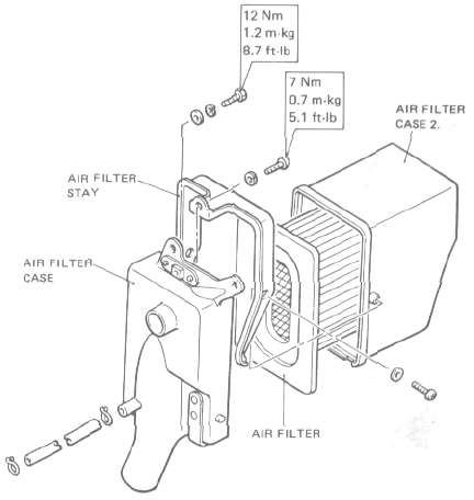
Air filter case & Surge tank |
Screw |
M4 P0.7 |
2 |
2 |
0.2 |
1.4 |
|
|
Clamp: |
|||||||
|
Turbo duct 1 & Turbocharger |
Screw |
M4 Po.7 |
1 |
2 |
0.2 |
1.4 |
|
Maintenance Specifications -- Electrical
Maintenance Specifications -- ElectricalC. Electrical
|
1. |
Voltage |
12V |
||
|
2. |
Ignition System |
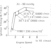
5°/1,050 r/min |
||
|
|
|
|
||
|
b. |
Advancer Type |
Electrical and vacuum controlled |
||
|
3. |
T.C.I. |
120Ω ± 20% at 20°C (68°F) |
||
|
4. c. |
Ignition Coil Primary Winding Resistance |
CM-12 09/HITACHI |
||
|
5. |
Charging System |
A.C. Generator |
||
|
6. |
Voltage Regulator |
I.C. type |
||
|
7. |
Rectifier |
S8534ATOSHIBA |
||


|
8. |
Battery |
12V 14AH |
|
9. |
-Electric Starter System |
Constant mesh type |
|
10. |
Horn |
Eddy type |
|
11. |
Flasher Relay |
Condenser type |
|
12. |
Self Cancelling Unit |
1A0/MATSUSHITA |
|
13. |
Oil Level Switch |
NIPPONDENSO |
|
14 |
Fuel Gauge |
NIPPON SEIKI |
|
15. |
Starting Circuit Cut Off Relay |
4H701/OMRON |
|
16. |
Emergency Engine Stop Relay |
4U8-00/OMRON |
|
17. |
Sidestand Relay |
4U800/OMRON |
| 18. a. b. c. |
Fuel Pump Relay Model /Manufacturer Coil Winding Resistance Color Code |
5A8-00/OMRON |
| 19. a. b. c. |
Fuel Pump Manufacturer Consumption Amperage Output Pressure |
NIPPONDENSO |
|
20.
|
Circuit Breaker |
Fuse 20A/1 pc.
|
General Torque Specifications and Conversion Tables
General Torque Specifications and Conversion TablesGeneral Torque Specification*
This chart specifies torque for standard fasteners with standard I.S.O. pitch threads. Torque specifications for special components or assemblies are included in the applicable sections of this book. To avoid warpage, tighten multi-fastener assemblies in a criss-cross fashion, in progressive stages, until full torque is reached. Unless otherwise specified, torque specifications call for clean, dry threads Components should be at room temperature.
|
A (Nut) |
B (Bolt) |
General torque specifications |
||
|
Nm |
m-kg |
ft-lb |
||
|
10 mm |
6 mm |
6 |
0.6 |
4.5 |
|
12 mm |
8 mm |
15 |
1.5 |
11 |
|
14 mm |
10 mm |
30 |
3.0 |
22 |
|
17 mm |
12 mm |
55 |
5.5 |
40 |
|
19 mm |
14 mm |
85 |
8.5 |
51 |
|
22 mm |
16 mm |
130 |
13.0 |
94 |
CONVERSION TABLES
CONVERSION TABLES
|
METRIC TO INCH SYSTEM |
|||
|
|
KNOWN |
MULTIPLIER |
RESULT |
|
TORQUE |
m-kg |
7.233 |
ft-lb |
|
m-kg |
86.80 |
in-lb |
|
|
cm-kg |
0.0723 |
ft-lb |
|
|
cm-kg |
0.8680 |
in-lb |
|
|
WT. |
kg |
2.205 |
lb |
|
9 |
0.03527 |
oz |
|
|
FLOW / DISTAMCE |
km/lit |
2.352 |
mpg |
|
km/hr |
0.6214 |
mph |
|
|
km |
0.6214 |
mi |
|
|
m |
3.281 |
ft |
|
|
m |
1.094 |
yd |
|
|
cm |
0.3937 |
in |
|
|
mm |
0.03937 |
in |
|
| VOLUME/
CAPACITY |
cc (cm3) |
0.03382 |
oz (US liq) |
|
cc (cm ) |
0.06102 |
cu. m |
|
|
lit (liter) |
2.1134 |
pt (US liq) |
|
|
lit (liter) |
1.057 |
qt (US liq) |
|
|
lit (liter) |
0.2642 |
gal (US liq) |
|
| MISC. |
kg/mm |
56.0C7 |
lb/in |
|
kg/cm |
14.2234 |
psi (lb/in2) |
|
| Centigrade (°C) | 9/5(°C) + 32 | Fahrenheit (° F) | |
|
INCH TO METRIC SYSTEM |
|||
|
|
KNOWN |
MULTIPLIER |
RESULT |
| TORQUE |
ft-lb |
0.13826 |
m-kg |
|
in-lb |
0.01152 |
m-kg |
|
|
ft-lb |
13.831 |
cm-kg |
|
|
in-lb |
1.1521 |
cm-kg |
|
|
WT. |
lb |
0.4535 |
kg |
|
oz |
28.352 |
g |
|
| FLOW /
DISTANCE |
mpg |
0.4252 |
km/lit |
|
mph |
1.609 |
km/hr |
|
|
mi |
1.609 |
km |
|
|
ft |
0.3048 |
m |
|
|
yd |
0.9141 |
m |
|
|
in |
2.54 |
cm |
|
|
in |
25.4 |
mm |
|
|
VOLUME / CAPACITY |
oz (US liq) |
29.57 |
cc (cm ) |
|
cu.in |
16.387 |
cc "cm ) |
|
|
pt (US liq) |
0.4732 |
lit (liter) |
|
|
qt (US liq) |
0.9461 |
lit (liter) |
|
|
gal (US liq) |
3.785 |
lit (liter) |
|
|
MISC. |
lb/in |
0.017855 |
kg/mm |
|
psi (lb/in ) |
0.07031 |
kg/cm2 |
|
|
Fahrenheit (°C) |
5/9(°F-32) |
Centigrade (°F) |
|
Consumer Information
Consumer InformationCONSUMER INFORMATION
Notice
The information presented represents results obtainable by skilled drivers under controlled road and vehicle conditions, and the information may not be correct under other conditions.
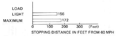
STOPPING DISTANCE
This figure indicates braking performance that can be met or exceeded by the vehicles to which it applies, without locking the wheels, under different conditions of loading and with partial failures of the braking system.
FULL OPERATIONAL SERVICE BRAKE
("Partial failure" information is not applicable and is not included)
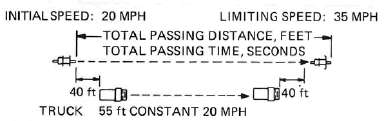
ACCELERATION AND PASSING ABILITY
This figure indicates passing times and distances that can be met or exceeded by the vehicles to which it applies, in the situations diagrammed below. The low-speed pass assumes an initial speed of 20 mph. and a limiting speed of 35 mph. This high-speed pass assumes an initial speed of 50 mph. and a limiting speed of 80 mph.
LOW-SPEED PASS
HIGH-SPEED PASS
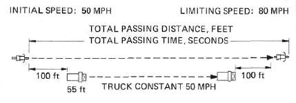
SUMMARY
Low-speed pass ........................................ 353.0 feet: 7.15 seconds
High-speed pass ........................................ 883.4 feet: 8.4 seconds
Parts Illustrations
Parts IllustrationsPARTS ILLUSTRATIONS
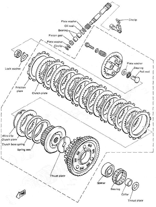
Clutch
ClutchCLUTCH
Transmission
Transmission
TRANSMISSION

Middle Gear Damper
Middle Gear DamperMIDDLE GEAR/DAMPER

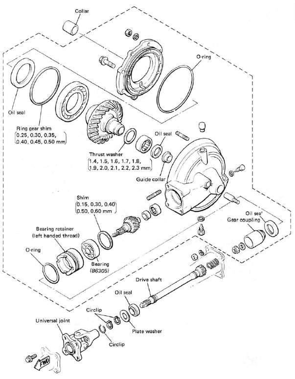
Final Gear / Driveshaft
Final Gear / DriveshaftFINAL GEAR / DRIVE SHAFT
Front Wheel
Front WheelFRONT WHEEL

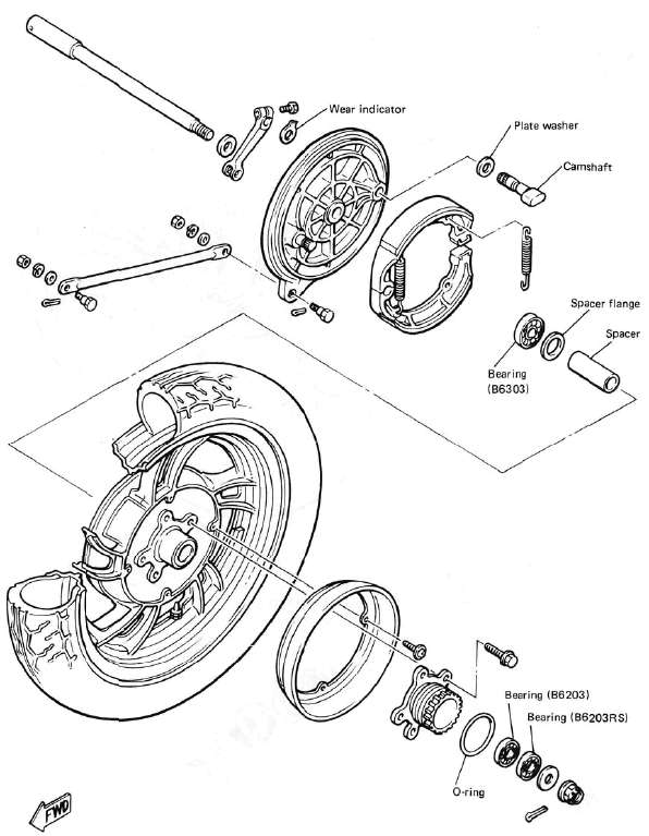
Rear Wheel
Rear WheelREAR WHEEL
Front Brake
Front BrakeFRONT BRAKE CALIPER
FRONT MASTER CYLINDER
Exhaust
ExhaustEXHAUST

Fairing Components
Fairing ComponentsHTML clipboard
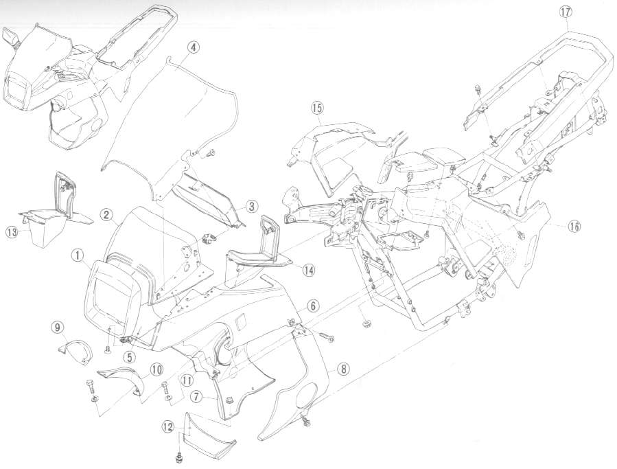
FAIRING COMPONENTS
|
No |
Part name |
|
1 |
Headlight nacelle |
|
2 |
Hood 1 |
|
3 |
Hood 2 |
|
4 |
Windscreen |
|
5 |
Upper panel right |
|
6 |
Upper panel left |
|
7 |
Lower panel Right |
|
B |
Lower panel (lefl) |
|
9 |
Air scoop (right) |
|
10 |
Air scoop (left) |
|
11 |
Oil cooler cover |
|
12 |
Skirt |
|
13 |
Console box (right) |
|
14 |
Console box (left) |
|
15 |
Sidepanel (right) |
|
16 |
Sidepanel (left) |
|
17 |
rear moulding |
Front Fork
Front ForkFRONT FORK

Fuel Pump
Fuel PumpFUEL PUMP

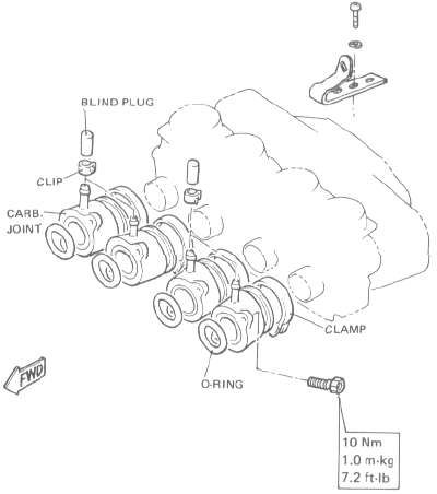
Intake
IntakeINTAKE
Middle Gear Damper
Middle Gear DamperMIDDLE GEAR/DAMPER
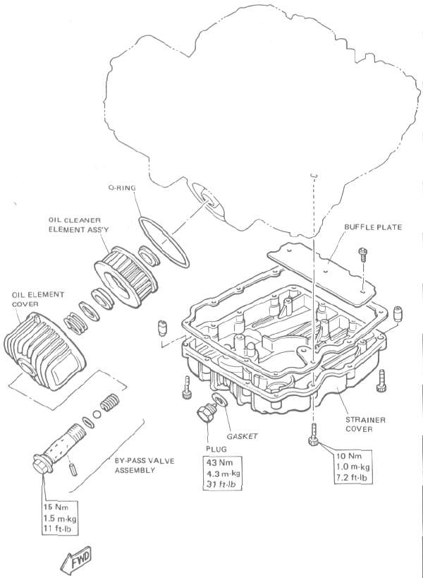
Oil Cleaner (Filter)
Oil Cleaner (Filter)HTML clipboard
OIL CLEANER
Oil Cooler
Oil CoolerOIL COOLER

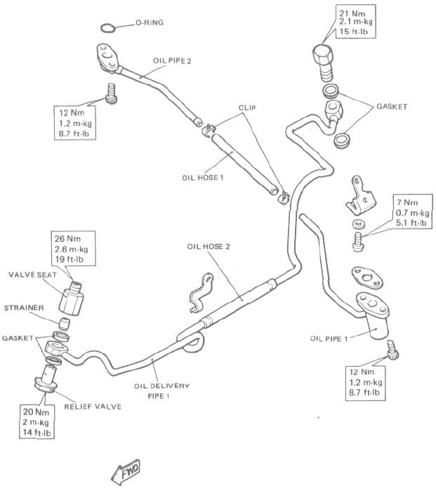
Oil Pipe for Turbo Unit
Oil Pipe for Turbo UnitOIL PIPE FOR TURBO UNIT
Rear Arm / Suspension
Rear Arm / SuspensionREAR ARM/SUSPENSION

Speedometer / Tachometer
Speedometer / TachometerSPEEDOMETER/TACHOMETER

Surge Tank
Surge TankSURGE TANK

NOTE: The mark on the turbo duct 2 should be aligned to the surge tank mark.

Electrical Component Locations
Electrical Component LocationsELECTRICAL 1
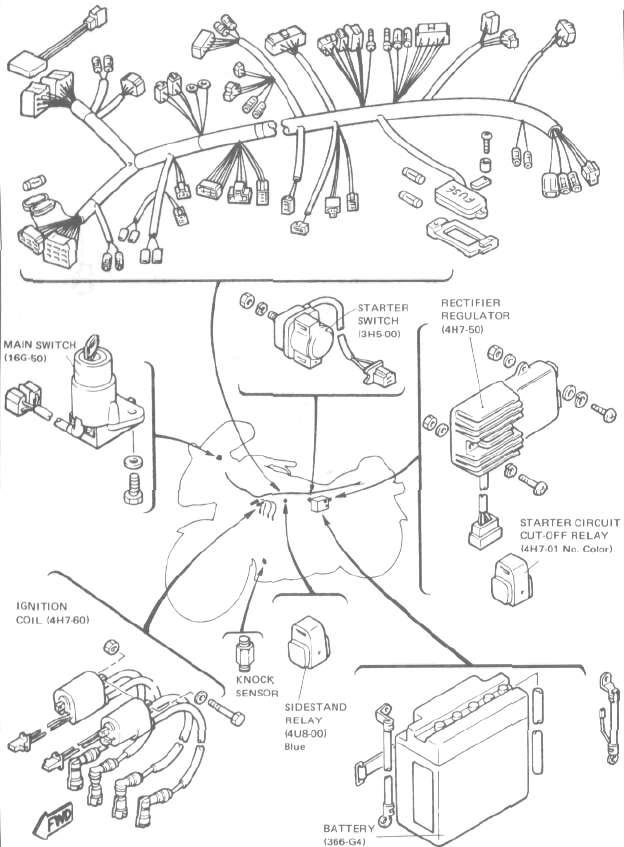
ELECTRICAL 2

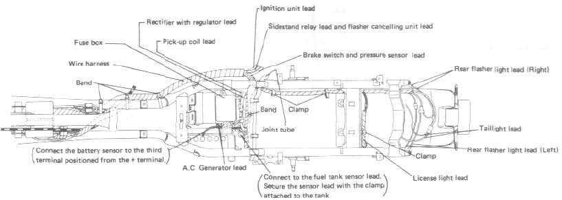
Cable Routing
Cable Routing


Turbo Wiring Diagram
Turbo Wiring Diagram

1. Main switch
2. Front brake switch
3. "START" switch
4. "ENGINE STOP" switch
5. Clutch switch
6. "TURN" switch
7. "HORN" switch
8. "LIGHT" (Dimmer) switch
9. Sidestand relay
10- Flasher relay
11. Cancelling unit
12. Fuse box
13. MAIN
14. HEAD
15. SIGNAL
16. IGNITION
17. Tail/brake light
18. License light
19. Rear flasher light
20. Battery sensor
21. Battery
22. Starter relay
23. Starter motor
24. Starter circuit cut-off relay
25. Emergency engine stop switch
26. Engine stop relay
27. Fuel pump relay
28. Fuel pump
29. Spark plug
30. Ignition coil
31. T.C.I, unit
32. Pick up coil
33. Rear brake switch
34. Rectifier/regulator
35. A.C. generator
36. Neutral switch
37. Boost pressure sensor
38. Knock sensor
39. Side stand switch
40. Fuel level sensor
41. Engine oil level sensor
42. Brake fluid level sensor
43. Diode
44. Horn
45. Front flasher light
46. Headlight
47. "CHECK" switch
48. "WARNING" control
49. Computerized monitor
50. "TURN" indicator light
51. "NEUTRAL" indicator light
52. "WARNING" indicator light
53. "HIGH BEAM" indicator light
54. Boost pressure gauge
55. Tachometer
56. Sender
57. Meter light
58. Meter assembly
59. Sealed wire outer, inner
COLOR CODE
|
Br |
Brown |
Y |
Yellow |
L |
Blue |
R/W |
Red/White |
Y/B |
Yellow/Black |
Y/R |
Yellow/Red |
E |
Ground |
|
R |
Red |
Dg |
Dark Green |
P |
Pink |
L/W |
Blue/White |
Br/W |
Brown/White |
R/W |
Red /White |
B/R |
Black/Red |
|
W |
White |
Ch |
Chocolate |
O |
Orange |
L/B |
Blue/Red |
Y/G |
Yellow/Green |
L/R |
Blue/ Red |
Gy |
Gray |
|
B |
Black |
Sb |
Sky Blue |
G |
Green |
R/Y |
Red/Yellow |
W/G |
White/Green |
G/Y |
Green/Yellow |
B/Y |
Black/ Yellow |