Chapter 3, ENGINE OVERHAULING
Chapter 3, ENGINE OVERHAULINGCHAPTER3. ENGINEOVERHAULING
Engine Removal
Engine RemovalENGINE REMOVAL
NOTE:
It is not necessary to remove the engine in order to remove the following components:
• Piston
• Clutch
• Carburetor
• Oil pump
PREPARATION FOR REMOVAL
1. Remove all dirt, mud, dust, and foreign material before removal and disassembly.
2. Use proper tools and cleaning equipment. Refer to CHAPTER 1, "SPECIAL TOOL"

NOTE:
When disassembling the engine, keep mated parts together. This includes gear, cylinders, pistons, and other parts that have been "mated" through normal wear. Mated parts must be reused as an assembly or replaced.
3. During the engine disassembly, clean all parts and place them in trays in the order of disassembly. This will speed up assembly time and help assure that all parts are correctly reinstalled in the engine.

SEAT AND FUEL TANK
1. Remove:
• Seat (1)
• Fuel tank (2)
• Left side cover (3)
2. Drain:
• Engine oil

BATTERY
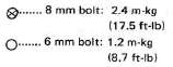
1. Disconnect:
• Battery leads (1),(2)
• Breather hose (3)
NOTE:
Disconnect the negative lead first.

EXHAUST PIPE AND MUFFLER
1. Remove:
• Nuts
2. Loosen:
• Clamp bolts
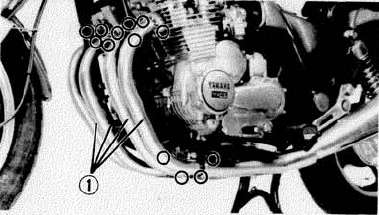
3. Remove:
• Exhaust pipes (1)
4. Remove:
• Chamber mount bolt (1)
• Muffler mount bolts (2)
• Muffler with chamber

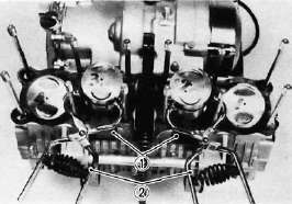
CARBURETOR AND CABLES
1. Loosen:
• Clamp screws
2. Remove:
• Air cleaner case (1) mount bolts (2)
3. Push the air cleaner case toward the rear to disconnect air outlet hoses from carburetors.

4. Disconnect:
• Choke cables (3)
5. Remove:
• Carburetors
• Throttle cable (4)
NOTE:
After removing the carburetors, cover the carburetors with a clean cloth to keep dust and dirt out.

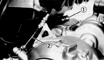
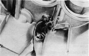
7. Disconnect:
• Crankcase ventilation hose (1) (from crankcase)
• Clutch cable (2)
CONNECTOR
1. Remove:
• Plate
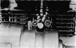
2. Disconnect:
• Pickup coil lead
• Generator lead
• Neutral switch lead
• Oil level switch lead
• Starter motor lead (1) (from starter motor)

SHIFT PEDAL BRAKE PEDAL, FOOTREST AND DRIVE SHAFT
1. Remove:
• Shift pedal (1)
• Left footrest (2)
2. Disconnect:
• Rubber boot (3)
3. Remove:
• Joint bolts (4)

4. Remove:
• Brake pedal (1)
• Right footrest (2)

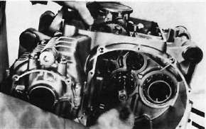
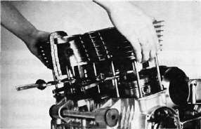
ENGINE REMOVAL
1. Place a suitable stand under the engine.
2. Remove:
• Mounting bolts
• Downtube frame (1)

3. Remove:
• Engine assembly (from chassis right side)

Cylinder Head Removal
Cylinder Head RemovalENGINE OVERHAUL
A. Cylinder Head and Cylinder
1. Remove the cylinder head cover.
2. Remove the left crankcase cover (pickup coil cover).
3. Remove the cam chain tensioner.
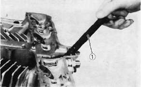
4. Use a 19 mm wrench on the timing plate flats to rotate the crankshaft counterclockwise until the engine is at T.D.C.
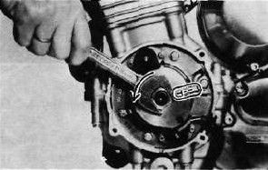
CAUTION:
Never use an alien wrench to rotate the crankshaft. Always use the 19 mm flats provided on the timing plate to rotate this engine.
5. Remove the four cam sprocket bolts.
6. Slip each sprocket off its mounting boss on the cam.
CAUTION:
From this point on, do not rotate the cam shaft or valve damage may occur. On this, it is not necessary to break the cam chain. However, it can be broken if so desired. It is easier to disassemble the engine without separating the chain.
7. Remove the cam chain guide.
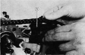
1. Cam chain guide
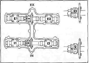
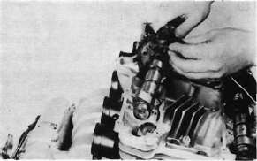
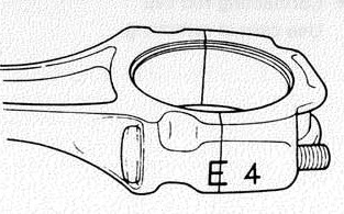
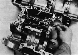
8. Remove the cam caps. Note the location of the cam caps. The caps for the intake cam shaft are identified 1-1 through I-3. The exhaust cam caps are identified E-1 through E-3. Directional arrows are cast on each cap and point toward the clutch side.
9. Fasten safety wire to the cam chain to prevent its falling into the crankcase cavity.
Slide the cams and sprockets from under the chain and remove the cams and sprockets.
10. Remove the front cam chain guide.
1. Front cam chain guide
11. Remove the spark plugs.
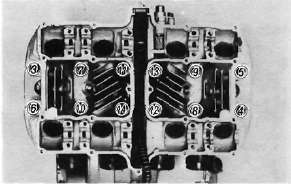
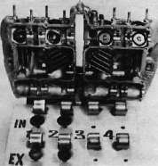
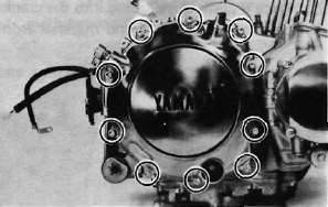
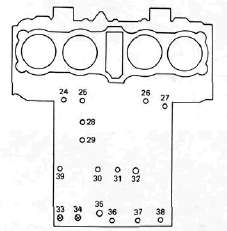
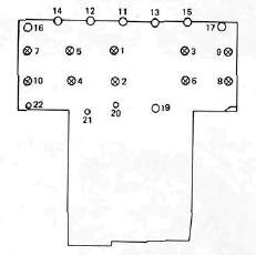
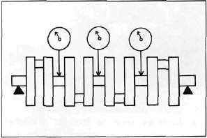
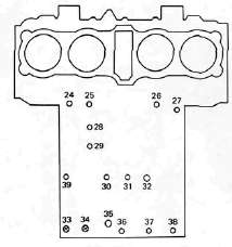
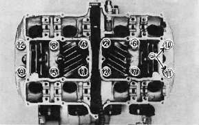
12. Remove the cylinder head bolts and nuts in the numerical order as shown. Start by loosening each nut 1/2 turn until all of the nuts are loose. Remove the cylinder head.
Cylinder and Cylinder Head Disassembly
Cylinder and Cylinder Head Disassembly
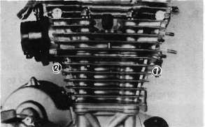
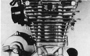
13. Remove the front cylinder holding nut and remove the cylinder assembly. It may be necessary to tap the cylinder lightly to loosen it from the base gasket.
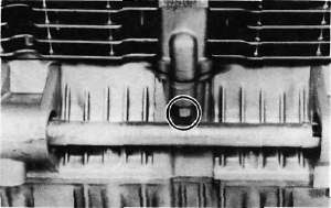
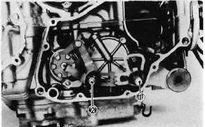
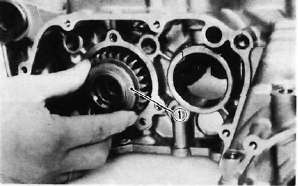
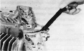
14. Remove the rear cam chain guide by loosening the holding bolt.
1. Holding bolt 2. Rear cam chain guide
B. Cylinder Head Disassembly
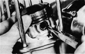
1. Remove the valve lifters and pads. Be careful not to scratch the lifter bodies or lifter bores in the cylinder head. Be very careful to identify each lifters position so that it may be returned to its original place.
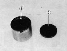
1. Valve filter 2. Adjusting pad
2. Mount the valve spring compressor on the head and depress each valve spring. Take out the retainer and valve spring with tweezers.
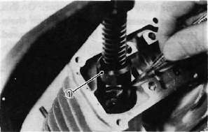
1. Valve spring compressor
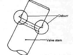
3. Remove valves.
NOTE:
Deburr any deformed valve stem end. Use an oil stone to smooth the stem end. This will help prevent damage to the valve guide during valve removal.
4. Use a small box to hold the parts and identify the original position of each lifter and valve. Be very careful not to mix the location of these components.
Piston, Pickup Coil, Shifter, Starter, Generator and Clutch Removal
Piston, Pickup Coil, Shifter, Starter, Generator and Clutch RemovalC. Piston
1. Mark each piston to aid in reassembly.
2. Place a clean towel or rag into the crank-case to keep circlips and material from falling into the engine.
3. Remove piston pin clips, piston pins, and pistons.
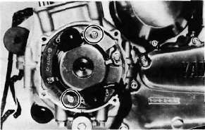
D. Pick-up Coil Assembly
1. Remove the alien bolt that holds the timing plate.
2. Remove the pick-up coil securing screws and remove the pick-up coil assembly.
E. Shifter
1. Remove the change pedal.
2. Remove the left crankcase cover.
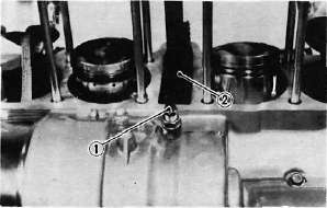
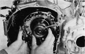
3. Remove the shift lever assembly and shift shaft assembly.
1. Shift lever assembly 2. Shift shaft assembly
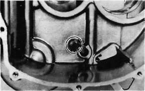
4. Remove the middle gear case oil level maintaining plug.
F. Starter Motor and Generator
1. Remove the starter motor securing bolts and remove the motor assembly.
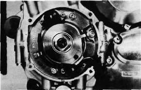
2. Remove the generator cover and stator coil assembly.

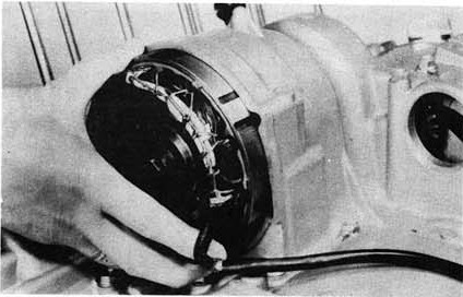
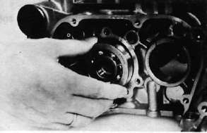
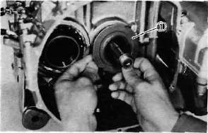
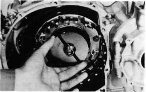
3. Install the rotor holding tool (special tool) on the rotor as shown and remove the rotor holding bolt.
1. Rotor holding tool
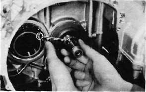
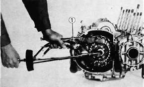
4. Invert the holding tool as shown and insert the rotor puller adapter (special tool) into the rotor shaft and screw in the rotor puller (special tool). Remove the rotor.

1. Rotor puller adapter
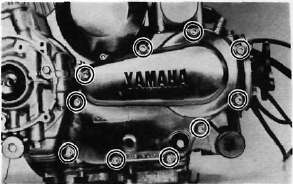
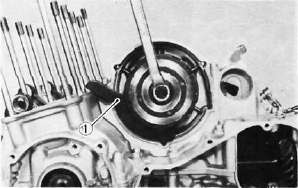
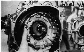
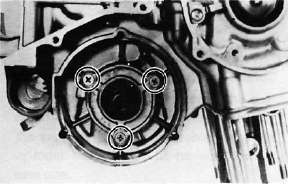
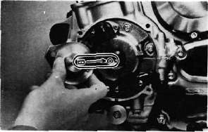
G. Clutch
1. Remove right crankcase cover.
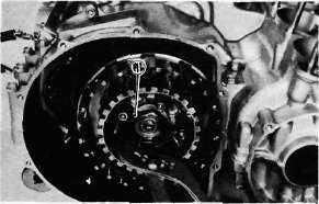
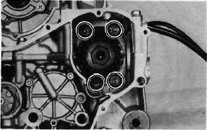
2. Release the tension evenly on the 6 mm bolts and remove the clutch pressure plate and clutch springs.
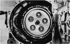
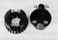
NOTE:
The outermost friction plate has a tab with a V-cut (1) in it. Give some identifying mark to the corresponding dog (2) in the clutch housing. This dog is the narrowest.

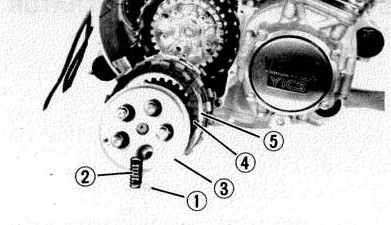
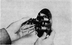
3. Remove the friction plates and clutch plates.
(1) Clutch spring bolts
(2) Clutch springs
(3) Pressure plate
(4) Friction plates
(5) Clutch plates
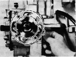
4. Straighten the lock washer tab. Use the clutch boss holder (special tool) to hold the clutch boss and remove the lock nut and lock washer.
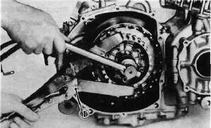
1. Clutch boss holder
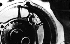
5. Remove the clutch boss and spacer.

6. Screw in a suitable length of 6 mm bolt into the one of the threaded holes on the collar and pull out the collar and needle bearing from the primary driven gear.
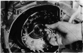
1. Collar
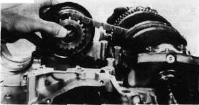
7. Remove the primary driven gear assembly and oil pump drive sprocket.
Oil Pump and Middle Gear Disassembly
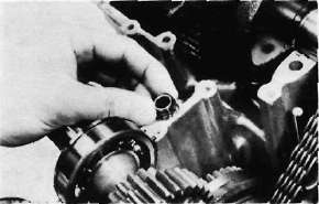
Oil Pump and Middle Gear DisassemblyH. Oil Pump Removal and Disassembly
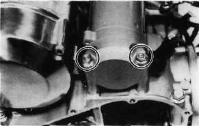
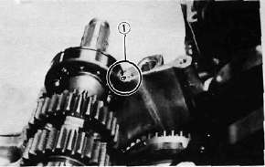
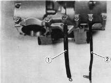
1. Remove the strainer cover. Note the wire harness clip position.
2a. Remove the oil pump securing bolts and remove the sprocket cover and oil pump assembly.

2b. Remove the Oil pump drive sprocket (1), Chain (2) Collar (3) and thrust plate.

CAUTION:
Do not attempt to remove the strainer screen as it is permanently fitted onto the pump housing. If the pump housing and/or any parts of the pump are damaged, the pump assembly must be replaced with a new one.
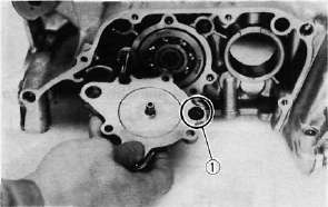
3. Remove the oil pump driven sprocket.

4. Remove the oil pump cover and rotor assembly.
5. Remove the pressure relief valve spring and plunger.

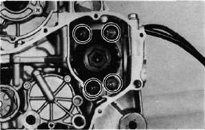
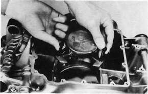
I. Middle Gear
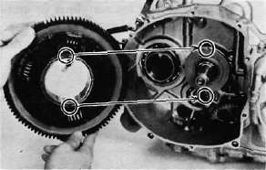
1. Remove the middle driven gear housing holding bolts.
2. Remove the middle driven gear housing assembly and shims.

NOTE:
If it is difficult to remove housing assembly, loosen the two crankcase bolts located near the middle driven gear housing.
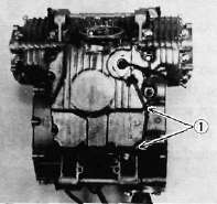
3. Remove "TORX" screws holding the middle drive gear assembly.
4. Remove the bearing retainers.
Upper Crankcase Disassembly
Upper Crankcase DisassemblyJ. Crankcase Disassembly
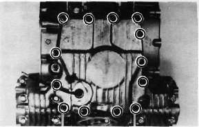
1. Remove the upper crankcase bolts, starting the highest numbered bolt. Turn over the engine and remove the lower crankcase bolts,
CRANKCASE TORQUE SEQUENCE
UPPER CASE
LOWERCASE
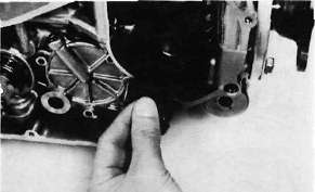
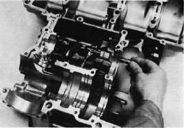
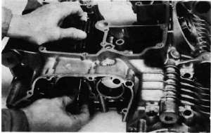
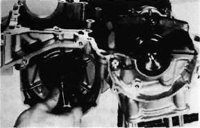
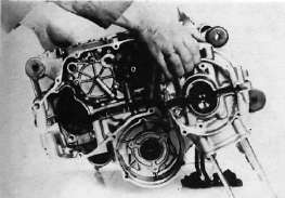
2. Separate the lower case from the engine. Use a soft rubber hammer to carefully separate the crankcase.
K. Upper Crankcase
1. Remove the middle drive gear and damper assembly.
2. Remove the transmission main shaft assembly.
3. Remove the A.C.G. shaft cover.
4, Remove the oil spray nozzle.
5. Carefully remove the A.C.G. shaft from the gear.
6. Remove the gear from the chain.
7. Straighten the lock washer tube and remove the bolt securing the starter idle gear shaft. Remove the shaft and starter idle gear.
Lower Crankcase Disassembly
Lower Crankcase DisassemblyL. Lower Crankcase
1. Remove the dowel pin and "O-ring".
2. Remove the shift fork guide bar and shift forks. The shift forks are identified by numbers cast on their sides.
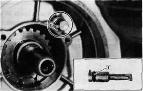
3. Remove the bolt securing the shift cam locating pin and remove the stopper plate and locating pin.
4. Remove the neutral switch.
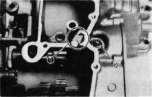
1. Shift cam locating pin 2. Neutral switch
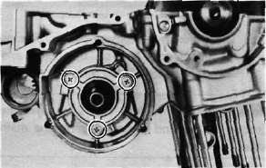
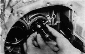
5. Pull out the shift cam.
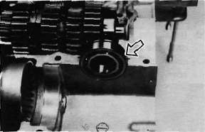
6. Remove the driven shaft bearing cover holding screws and remove the bearing cover.
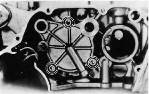
7. Remove the bearing and 5th wheel gear from the driven shaft and pull out the driven shaft assembly.
1. 5th wheel gear
Cylinder Head and Valves -- Inspection & Repair
Cylinder Head and Valves -- Inspection & RepairINSPECTION AND REPAIR
A. Cylinder Head Cover
Place head cover on a surface plate. There should be no warpage. Correct by re-surfacing as follows:
Place #400 or #600 grit wet sandpaper on surface plate and re-surface head cover using a figure-eight sanding pattern. Rotate head cover several times to avoid removing too much material from one side.
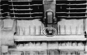
B. Cylinder Head
1. Using a rounded scraper, remove carbon deposits from combustion chamber. Take care to avoid damaging spark plug threads and valve seats. Do not use a sharp instrument. Avoid scratching the aluminum.
2. Check the cylinder head warpage with a straight edge as shown.

The warpage should not exceed the specified limit, if necessary resurface. If the warpage exceeds allowable limit, the cylinder head should be replaced with a new one.
Cylinder head warpage: less than 0.03 mm (0.0012 in)
Allowable limit: 0.25 mm (0.010 in)
C. Valve, Valve Guide, and Valve Seat
1a. Check the valve face and the stem end for wear. If the valve face and/or the stem end are pitted or worn, regrind the valve with a valve refacer. Replace the valve if any dimension exceeds the specifications:
(1) 0.7 mm (0.028 in) Minimum Thickness (service limit)
(2) 0.5mm (0.020 in) bevel
(3) 4.0mm (0.157 in) Minimum Length (Service limit)

1b. Measure the contacting mark position on the valve face (1) and verify it is 0.3 mm (0.12 in) from the edge and 1.0mm +/- 0.1mm (0.039 +/- 0.004 in) wide. If it is out of range, the valve seat should be recut as detailed below.

2. Valve stem wear must be measured and then combined with valve guide measurements to guide clearance. This clearance must be within tolerances. If it exceeds the maximum limit, then replace either or both valve and guide, as necessary.

|
|
Valve Stem Clearance |
Maximum |
|
Intake |
0.010 — 0.037 mm (0.0004-0.0015 in) |
0.10 mm (0.004 in) |
|
Exhaust |
0.025-0.052 mm (0.0010-0.0020 in) |
0.12 mm (0.005 in) |
3. Valve stem end
Inspect the end of the valve stem. If the end appears to be "mushroomed" or has a larger diameter than the rest of the stem, the valve, valve guide, and oil seal should be replaced.
4. Turn valve on "V" blocks and measure the amount of stem runout with a dial gauge. If it exceeds the maximum limit, replace the valve.
Maximum valve stem runout: 0.03 mm (0.0012 in)

5. Valve guide and valve oil seal replacement If oil leaks into the cylinder through a valve due to a worn valve guide, or if a valve is replaced, the valve guide should also be replaced.
NOTE:
The valve oil seal should be replaced whenever a valve is removed or replaced.
a. Measure valve guide inside diameter with a small bore gauge. If it exceeds the limit, replace with an oversize valve guide.
Guide diameter (I.D.):
Limit: 7.10 mm (0.280 in)
b. To ease guide removal and reinstallation, and to maintain the correct interference fit, heat the head to 100t (212°F). Use an oven to avoid any possibility of head warpage due to uneven heating.
c. Use the appropriate shouldered punch (special tool) to drive the old guide out and drive the new guide in.
NOTE:
When a valve guide is replaced, the O-ring should also be replaced.

1. Valve guide remover 2. Valve guide installer
d. After installing the valve guide, use the 7 mm reamer (special tool) to obtain the proper valve guide to valve stem clearance.

e. After installing the valve guide in the cylinder head, the valve seat must be recut. The valve should be lapped to the new seat.
6. Grinding the Valve Seat
a. The valve seat is subject to severe wear. Whenever the valve is replaced or the valve face is re-surfaced (see caution) the valve seat should be re-surfaced at a 45° angle. If a new valve guide has been installed the valve seat must be recut to guarantee complete sealing between the valve face and seat.

CAUTION:
If the valve seat is obviously pitted or worn, it should be cleaned with a valve seat cutter. Use the 45° cutter, and when twisting the cutter, keep an even downward pressure to prevent chatter marks.
If cutting section "A" of the valve seat, use 30° cutter. If cutting section "B", use the 45° cutter. If cutting section "C" use 60° cutter. b. Measure valve seat width. Apply mechanic's bluing dye (such as Dykem) to the valve face and valve seat, apply a very small amount of fine grinding compound around the surface of the valve face insert the valve into position, and spin the valve quickly back and forth. Lift the valve, clean off all grinding compound, and check valve seat width. The valve seat and valve face will have removed bluing wherever they contacted each other. Measure the seat width with vernier calipers. It should measure approximately 1.1 mm (0.0433 in). Also, the seat should be uniform in contact area. If valve seat width varies, or if pits still exist, further cutting will be necessary. Remove just enough material to achieve a satisfactory seat.
|
|
Standard Width |
Wear Limit |
|
Seat width |
1.0 ±0.1 mm (0.0394 ± 0.0039in) |
1.4 mm (0.055 in) |

a. Seat width
c. If the valve seat is uniform around the perimeter of the valve face, but is too wide or not centered on the valve face, it must be altered. Use either the 30°, 45° or 60° cutters to correct the improper
seat location in the manner described below:

1) If the valve face shows that the valve seat is centered on the valve face, but too wide, then lightly use both the 30° and the 60° cutters to reduce the seat width to 1.1 mm (0.0433 in).

1. Valve seat cutter
2) If the seat shows to be in the middle of the valve face, but too narrow, use the 45°cutter until the width equals 1.1 mm(0.0433 in).
3) If the seat is too narrow and right up near the valve margin, then first use the 30° cutter and then the 45° cutter to get the correct seat width.
4) If the seat is too narrow and down near the bottom edge of the valve face, then first use the 60° cutter and then the 45° cutter.
7. Lapping the valve/valve seat assembly a. The valve/valve seat assembly should be lapped if neither the seat nor the valve face are severely worn.
b. Apply asmall amount of coarse lapping compound to valve face. Insert the valve into the head. Rotate the valve until the valve and valve seat are evenly polished. Clean off the coarse compound, then follow the same procedure with fine compound.
Continue lapping until the valve face shows a complete and smooth surface all the way around. Clean off the compound material. Apply bluing dye to the valve face and seat and rotate the valve face for full seat contact which is indicated by a grey surface all around the valve face where the bluing has been rubbed away.
c. Valve leakage check
After all work has been performed on the valve and valve seat, and all head parts have been assembled, check for proper valve/valve seat sealing by pouring solvent into each of the intake ports, then the exhaust ports. There should be no leakage past the seat. If fluid leaks, disassemble and continue to lap with fine lapping compound. Clean all parts thoroughly, reassemble and check again with solvent. Repeat this procedure as often as necessary to obtain a satisfactory seal.
Valve Springs and Lifters, Camshafts, Chain and Guides -- Inspection and Repair
Valve Springs and Lifters, Camshafts, Chain and Guides -- Inspection and RepairD. Valve Spring and Lifters
1. Checking the valve springs
a. This engine uses two springs of different sizes to prevent valve float or surging. The valve spring specifications show the basic value characteristics.
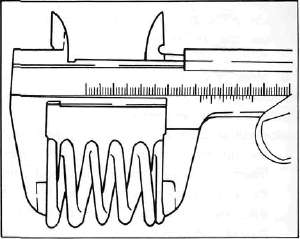
b. Even though the spring is constructed of durable spring steel, it gradually loses some of it's tension. This is evidenced by a gradual shortening of free length. Use a vernier caliper to measure spring free length. If the free length of any spring has decreased more than 2 mm (0.080 in) from its specification replace it.
c. Another symptom of a fatigued spring is insufficient spring pressure when compressed. This can be checked using a valve spring compression rate gauge. Test each spring individually. Place it in the gauge and compress the spring first to the specified compressed length with the valve closed (all spring specifications can be found in the previous section, Valve Spring), then to the length with the valve open. Note the poundage indicated on the scale at each setting. Use this procedure with the outer springs, then the inner springs.
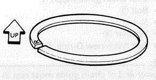
NOTE:
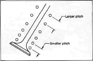
All valve springs must be installed with larger pitch upward as shown.
|
Valve Spring Specifications |
||
|
|
OUTER |
INNER |
|
Free length |
37.0 mm (1.457 in) |
33.5 mm (1.319 in) |
|
Installed length (valve closed) |
34.0 mm (1.339 in) |
31.0 mm (1.220 in) |
|
Installed pressure |
17.2 kg -21.0 (37.9 - 46.3 lb) |
8.1 - 9.9 kg (17.9 - 21.8 1b) |
|
Allowable tilt from vertical |
1.6° |
|
2. Valve lifter
a. Check each valve lifter for scratches or other damage. If the lifter is damaged in any way, the cylinder head surface in which it rides is probably also damaged. If the damage is severe, it may be necessary to replace both the lifter and the cylinder head.
NOTE:
For proper valve lifter-to-head clearance, always install lifters on their original valves.
E. Camshafts, Cam chain and Cam Sprockets
1. Camshaft
a. The cam lobe metal surface may have a blue discoloration due to excessive friction. The metal surface could also start to flake off or become pitted.
b. If any of the above wear conditions are readily visible, the camshaft should be replaced.
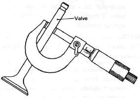
c. Even though the cam lobe surface appears to be in satisfactory condition, the lobes should be measured with a micrometer. Cam lobe wear can occur without scarring the surface. If this wear exceeds a pre-determined amount, valve timing and lift are affected. Replace the camshaft if wear exceeds the limits.
| Cam Lobe A | Cam Lobe B | |
| Intake | 36.8 mm (1.449 in) | 28.1 mm (1.106 in) |
| Exhaust | 36.3 mm (1.429 in) | 28.06 mm (1.105 in) |

d. Install the camshaft on the cylinder head. Place a strip of Plastigage between camshaft and camshaft cap as illustrated (lengthwise along camshaft). Tighten the nuts with specified torque. Remove the camshaft cap and determine the clearance by measuring the width of the flattened Plastigage.
Cap nut tightening torque: 1.0m-kg(7.2ft-lb)
1. Plastigage
NOTE:
Do not turn camshaft when measuring clearance with Plastigage.
Camshaft-to-cap clearance:
|
Standard: |
0.020-0.054 mm |
|
|
(0.0008- 0.0021 in) |
|
Maximum: |
0.160 mm (0.006 in) |
If the camshaft-to-cap clearance exceeds specification, measure camshaft bearing surface diameter.
Bearing surface diameter:
|
Standard: |
24.967-24.980 mm |
|
|
(0.9830-0.9835 in) |
1) If camshaft diameter is less than specification, causing excessive clearance, replace camshaft.
2) If camshaft is within specification and camshaft-to-cap clearance is excessive, replace cylinder head.
2. Cam chain
Except in cases of oil starvation, the cam chain wears very little. If the cam chain has stretched excessively and it is difficult to keep the proper cam chain tension, the chain should be replaced.
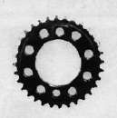
3. Cam sprockets
Check cam sprockets for obvious wear.
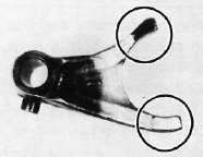
4, Cam chain dampers
Inspect the top cam chain damper (stopper guide) and two (2) vertical (slipper-type) dampers for excessive wear. Any that shows excessive wear should be replaced. Worn dampers may indicate an improperly adjusted or worn-out cam chain.

(1) Upper guide
(2) Front guide
(3) Rear guide
5 Automatic Cam Chain Tensioner
Ensure operation is one-way and smooth. Inspect all parts for wear or damage

(1) End plug
(2) Washer
(3) Springs
(4) Tensioner body
(5) One way cam
(6) Tensioner rod
Cylinder and Piston -- Inspection and Repair
Cylinder and Piston -- Inspection and Repair. Cylinder
1. Inspect the cylinder walls for scratches. If vertical scratches are evident, the cylinder wall should be rebored or the cylinder should be replaced.
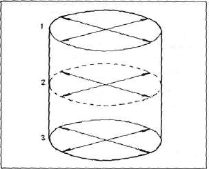
2. Measure cylinder wall wear as shown. If wear is excessive, compression pressure will decrease. Rebore the cylinder wall and replace the piston and piston rings. Cylinder wear should be measured at three depths with a cylinder bore gauge. (See illustration.)
|
|
Standard |
Wear Limit |
|
Cylinder bore |
65.00 mm (2.5591 in) |
65.005 mm (2.5592 in) |
|
Cylinder taper |
— |
0.05 mm (0.002 in) |
|
Cylinder out-of-round |
— |
0.01 mm (0.0004 in) |
If the cylinder wall is worn more than the wear limit, it should be rebored.
G. Piston andPiston Rings
1. Piston
a. Measure the outside diameter of the piston at the piston skirt. Measurement should be made at a point 7.5 mm (0.3 in) above the bottom edge of the piston. Place the micrometer at right angles to the piston pin.
|
Standard |
64.955 - 64.970 mm (2.5573 - 2.5579 in) |
|
Oversize 1 |
65.5 mm (2.58 in) |
|
Oversize 2 |
66.0 mm (2.60 in) |
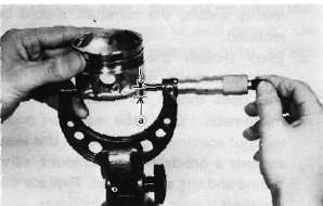
a. 7.5 mm (0.3 in)
b. Determine piston clearance as follows:
Minimum bore measurement — Maximum piston measurement * Piston clearance
EXAMPLE:
63.0 mm (2.4803 in) - 62.96 mm (2.4787 in)= 0.04 mm (0.0016 in)
Piston clearance
Piston clearance:
Standard: 0.030 - 0.050 mm (0.0012 - 0.0020 in)
Service limit: 0.1 mm (0.0039 in)
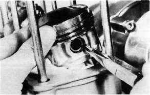
c. Piston ring/ring groove fit must have correct clearance. If the piston and ring have already been used, the ring must be removed and the ring groove cleaned of carbon. The ring should then be reinstalled. Use a feeler gauge to measure the gap between the ring and the land.
|
Side clearance |
Top |
0.03- 0.07 mm (0.0012- 0.0028 in) |
|
2nd |
0.02-0.06 mm (0.0008- 0.0024 in) |

1. Feeler gauge
2. Piston ring
a. The oversize top and middle ring sizes are stamped on top of the ring.
| Oversize 2 | 0.50 mm (0.0197 in) |
| Oversize 4 | 1.00 mm (0.0394 in) |
b. The expander spacer of the bottom ring (oil control ring) is color-coded to identify sizes.
The color mark is painted on the expander spacer.
|
Size |
Color |
| Oversize 2 | Blue |
| Oversize 4 | Yellow |
c. Push the ring into the bore and check end gap clearance with a feeler gauge.
NOTE:
The end gap on the expander spacer of the oil control ring is unmeasurable. If the oil control ring rails show excessive gap, all three components should be replaced.
|
|
||
|
|
Standard |
Limit |
|
Top/2nd ring |
0.15 — 0.30 mm (0.006- 0.012 in) |
1.0 mm (0.04 in) |
|
Oil control (Rails) |
0.2-0.7 mm (0.008-0.028 in) |
--- |
H. Piston Pin
1. Apply a light film of oil to pin. Install in connecting rod small end. Check for play. There should be no noticeable vertical play. If play exists, check connecting rod small end for wear. Replace pin and connecting rod as required.
2. The piston pin should have no noticeable free play in piston. If the piston pin is loose, replace the pin and/or the piston.
Crankshaft, Con rods and Bearings -- Inspection and Repair
Crankshaft, Con rods and Bearings -- Inspection and RepairI. Crankshaft
1. Crankshaft run-out
Support the crankshaft at both ends on V-blocks. Measure the amount of crankshaft run-out on the main bearing journals with a dial gauge while rotating crankshaft.
Run-out limit: 0.030 mm (0.0012 in)
If run-out exceeds limit, replace crankshaft.
2. Inspection of bearings
Check the bearings. If the inner or outer surface is burned, flaked, rough, scratched or worn, the bearings should be replaced.
3. Measuring main bearing oil clearance
a. Clean all crankshaft and crankcase journal surfaces.
b. Place upper crankcase half upside-down on a bench. Install bearing inserts into top crankcase.
c. Install crankshaft into upper crankcase.
d. Place Plastigage on crankshaft journal surface to be inspected.
NOTE:
Do not move crankshaft until clearance check has been completed.
e. Install bearings into bottom crankcase. Carefully, place lower crankcase onto upper crankcase.
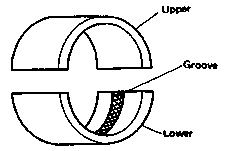
The crankshaft main bearing which has no groove on the bearing surface should be installed in the upper crankcase.
f. Install crankcase holding bolts 1 through 10. Tighten to full torque in torque sequence cast on crankcase.
Crankcase torque (8 mm bolt): 2.4 m-kg (17 ft-lb)

g. Remove bolts in reverse assembly order (10,9,8... etc.)
h. Carefully remove lower crankcase. Measure width of Plastigage on crankshaft journals to determine clearance.
Main bearing oil clearance: 0.020 - 0.044 mm (0.0008-0.0017 in)
1. Plastigage
4. Crankshaft main bearing selection a. Numbers used to indicate crankshaft journal sizes are stamped on the L.H. crank web. The first five (5) are main bearing journal numbers, starting with the left journal. The four (4) rod bearing journal numbers follow in the same sequence.

For greater clarity:

The upper crankcase half is numbered 4, 5, or 6 as shown.

1. Main bearing numbers
b. The connecting rods are numbered 3 or 4. The numbers for rods are stamped with ink on the rod itself.
1. Connecting rod size number
c. The proper bearing selection is made by subtracting the crankshaft journal number from the crankcase or rod size number. Use the color code to choose the proper bearing.
EXAMPLE:
Rod No. (Minus) Journal No. = Bearing No. 5-2 = 3 No. 3 bearing is Brown. Use Brown bearing inserts.
|
BEARING COLOR CODE |
|
|
No. 1 |
Blue |
|
No. 2 |
Black |
|
No. 3 |
Brown |
|
No. 4 |
Green |
|
*No. 5 |
Yello |
#For crankshaft main bearing only.
d. When assembling, apply a liberal coat of motor oil to all bearing surfaces.
NOTE:
When applying final torque to the rod caps, observe the following procedures:
e. Be sure the letter on both components align to form a perfect character:
f. Apply molybdenum disulfide grease to connecting rod bolt threads. Apply torque evenly to both ends of the cap. While tightening, if a torque of 2.0 m-kg (14.5 ft-lb) or more is reached, DO NOT STOP tightening until final torque is reached. If tightening is interrupted between 2.0 m-kg and 2.5 m-kg, loosen the nut to less than 2.0 m-kg and start again. Tighten to full torque specification (25 m-kg, 18 ft-lb) without pausing.
Oil Pump and Clutch -- Inspection and Repair
Oil Pump and Clutch -- Inspection and RepairJ. Oil Pump
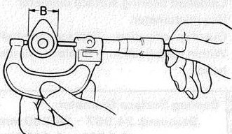
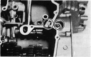
1. Check the clearance between housing and outer rotor.
Standard clearance B : 0.03 ~ 0.08 mm (0.0012 ~ 0.0031 in)
2. Check the clearance between outer rotor and inner rotor.
Standard clearance: 0.03 - 0.09 mm (0.001 - 0.003 in)
3 Check the rotor to housing clearance using a straight-edge.
Standard clearance: 0.03 - 0.08 mm (0.001 - 0.003 in)

4. Check the plunger for scratches and wear.

1. Relief valve plunger
K. Clutch
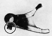
1. Clutch housing
a. Check the dogs on the clutch housing. Look for cracks and signs of galling on edges. If damage is moderate, deburr. If severe, replace the clutch housing.
NOTE:
Galling on the friction plate dogs of the clutch housing will cause erratic clutch operation. These can be dressed with a flat file using the indentations as a guide for depth.

b. Check the clutch housing bearing for damage. If damaged replace bearing.
2. Clutch boss
a. The clutch boss contains a built-in damper beneath the first clutch plate (clutch plate 2). It is not normally necessary to remove the circlip and disassemble the built-in damper unless there is serious clutch chattering.
b. Check splines on clutch boss for galling. If damage is slight to moderate, deburr; if it is severe, replace clutch boss.
NOTE:
Galling on clutch plate splines will cause erratic operation.

3. Friction and clutch plates
Check clutch steel plates and friction plates for heat damage. Measure friction plate thickness at 3 or 4 points. Measure clutch plates for warpage with a dial gauge and stand. Replace clutch plate or friction plates as a set if any is faulty or beyond wear limits.
|
|
Standard |
Wear limit |
|
Friction plate thickness |
3.0 mm (0.12 in) |
2.8 mm (0.11 in) |
|
Clutch plate warp limit |
— |
0.05 mm (0.0020 in) |


1. Feeler gauge
4. Clutch actuating mechanism

1. Plate washer 2. Thrust bearing 3. Pull rod
a. Check the pull rod rack gear teeth for wear and damage, replace if damaged.
b. Check the pull rod thrust bearing for damage, replace if damaged.
c. Check the clutch lever shaft pinion gear teeth for damage, replace if damaged.
5. Clutch springs
Measure the clutch spring free length. Replace the springs as a set if any is less than minimum free length.
Clutch spring minimum length: 50.1 mm (1.969 in)
Transmission -- Inspection and Repair
Transmission -- Inspection and RepairL. Transmission
1. Inspect each shift fork for signs of galling on gear contact surfaces. Check for bending. Make sure each fork slides freely on its guide bar.
2. Roll the guide bar across a surface place. If the bar is bent, replace.
3. Check the shift cam grooves for signs of wear or damage. If any profile has excessive wear and/or damage, replace cam.

4. Check the cam followers on each shift fork for wear. Check the ends that ride in the grooves in the shift cam. If they are worn or damaged, replace the shift forks.
5. Check shift cam dowel pins and side plate for looseness, damage or wear. Replace as required.
6. Check the shift cam stopper plate and circlip and stopper for wear. Replace as required.
7. Check the transmission shafts using a centering device and dial gauge. If any shaft is bent beyond specified limit, replace shaft.
Maximum run-out: 0.08 mm (0.0031 in)
8. Carefully inspect each gear. Look for signs of obvious heat damage (blue discoloration). Check the gear teeth for signs of pitting, galling or other extreme wear. Replace as required.
9. Check to see that each gear moves freely on its shaft.
10. Check to see that all washers and clips are properly installed and undamaged. Replace bent or loose clips and bent washers.
11. Check to see that each gear properly engages its counterpart on the shaft. Check the mating dogs for rounded edges, cracks, or missing portions. Replace as required.
M. Starter Drivers

1. Electric starter clutch and gears
a. Check the surface of the idle gear for pitting or other damage. If severe, replace the gear.
b. Check the spring caps and the springs for deformation or damage. If severe, replace as necessary.
c. Check the starter clutch bolts (alien screw) for looseness. If loose, remove the bolts and replace with new bolts. Apply a thread locking compound such as "LOCTITE" to threads and tighten to specified torque. Stake over the end of the bolts.
Starter clutch bolt torque: 3.0 m-kg (21.7 ft-lb)
d. Check the "HY-VO" chain for damage and wear, replace if damaged.
e. Check the "HY-VO" chainguide for damage, replace if damaged.
N. Crankcases and Strainer Cover
1. Check crankcase for cracks or other damage.
2. Clean all oil passages and blow out with compressed air.
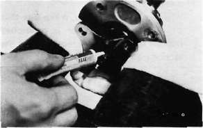
3. Strainer cover: Apply a thread locking compound such as "LOCTITE" to strainer cover bolts during reassembly.
O. Bearing and Oil Seals
1. After cleaning and lubricating bearings, rotate inner race with a finger. If rough spots are felt, replace the bearing.
NOTE:
Bearings are most easily removed or installed if the housings are first heated to approximately 95°~12E?C (200°~250°F). Bring the case up to proper temperature slowly. Use an oven to avoid distortion.
2. Check oil seal lips for damage and wear. Replace as required.
Middle Gear -- Inspection and Repair
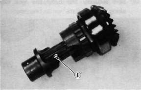
Middle Gear -- Inspection and RepairP. Middle Gear
1. Damper disassembly
NOTE:
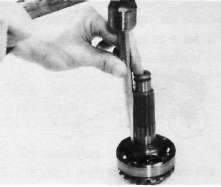
Disassembly of the middle gear damper requires the damper compressor (special tool) and a hydraulic press.
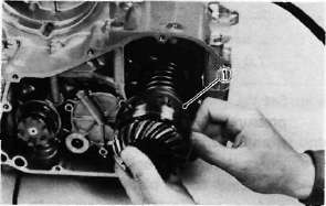
a. Place the middle drive shaft in a press with the damper compressor (special tool) in place as shown.
1. Damper compressor
b. Press the damper spring and remove the spring retainers.
c. Remove the spring seat, spring, and damper cams from the drive shaft.
2. Inspection
a. Inspect the damper cam surfaces. Check for smooth cam action and excessive wear on the cam surface. If cam surface is severely worn, replace damper assembly.
b. Inspect the damper spring for fatigue, wear and damage. Replace as necessary.
c. Check bearing movement for damage to balls, rouge spots, bearing looseness. Inspect gear teeth. If any gear tooth and/or bearing are damaged, the gear set and/or bearing must be replaced.
3. Middle drive/driven shaft bearing removal
CAUTION:
The following procedures should be performed only if the bearing or gear is to be replaced.
a. Middle drive gear
1) Bend down the locking collar of the nut with a suitable center punch.
2) Support the middle drive shaft holder (special tool) in a vise securely and put the drive pinion on it as shown. Remove the bearing holding nut with the 46 mm socket (special socket) and remove the bearing.
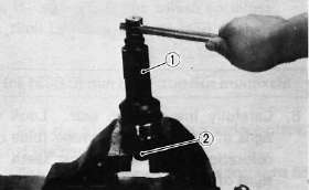
1. Middle drive shaft nut wrench (46 mm socket)
2. Middle drive shaft holder
b. Middle driven gear
1) Support the drive flange in a vise securely. Remove the flange holding nut.
CAUTION:
This holding nut has been locked with a thread locking compound, when reinstalling do not forget to apply a thread locking compound such as "LOCTITE" and punch.
2) Remove the drive flange from the driven shaft.
NOTE:
Driven gear shaft bearing should be replaced together with a bearing housing.
4. Middle gear reassembly
a. Middle drive gear bearing and damper
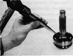
1) Install the bearing onto the drive pinion and secure it with a new lock nut using the middle drive shaft holder and special socket.
Tightening torque: 11 m-kg (80 ft-lb)
2) Stake the locking collar of the nut to the slot on the drive pinion shaft.
3) Install the driven damper cam onto the drive pinion shaft with the cam lobes positioned 90° from the row of shaft oil holes. Positioning tolerance is ± 1 spline (15°) from the 90° position.
1. Oil hole
4) Install the drive damper cams, spring, spring seat, and retainers using a press and the damper compressor.
b. Middle driven gear
1) Install the new bearing housing assembly onto the driven pinion shaft.
CAUTION:
Do not press the bearing outer race. Always press the inner race with care when installing.
2) Install the drive flange and new "O-ring" onto the driven gear shaft. Apply a thread locking compound such as "LOCTITE" to the shaft threads and tighten the nut to the specified torque.
Tightening torque: 12 m-kg (87 ft-lb)
3) Stake the nut with a center punch to lock as shown.
4) Install the new "O-ring" onto the bearing housing.
Upper Crankcase Reassembly
Upper Crankcase ReassemblyENGINE ASSEMBLY AND ADJUSTMENT
A. Important Information
1. Gasket and seal
All gaskets and seals should be replaced when an engine is overhauled. All gasket surfaces and oil seal lips must be cleaned.
2. Properly oil all mating engine and transmission parts and bearings during reassembly.
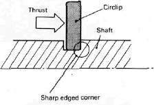
3. Circlip
All circlips should be inspected carefully before reassembly. Always replace piston pin clips after one use. Replace distorted circlips.
When installing a circlip, make sure that the sharp edged corner is positioned opposit to the thrust it receives. See the sectional view below.
4. Lock washer/plate and cotter pin
All lock washers/plates and cotter pins must be replaced when they are removed. Lock washer/plate tab(s) should be bent over along the bolt or nut flat(s) after tightening the bolt or nut properly (see illustration).
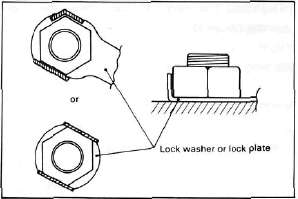
Cotter pins should be replaced after one use.
B. Engine Assembly
1. Upper crankcase
a. Install the connecting rods onto the crankshaft with the proper connecting rod bearings. Apply oil to bearings and molybedenum disulfide grease to the bolt threads. Apply torque evenly to both ends of the cap.
CAUTION:
While tightening, if a torque of 2.0 m-kg (14.5 ft-lb) or more is reached, DO NOT STOP tightening until final torque is reached.
If tightening is interrupted between 2.0 m-kg and 2.5 m-kg, loosen the nut to less than 2.0 m-kg and start again. Tighten to full torque specification without pausing.
Rod cap torque: 2.5 m-kg (18.1 ft-lb)
b- Install the proper cankshaft main bearings into the crankcase and place the crankshaft. Oil the bearings liberaly.
NOTE:
Do not forget to install the crankshaft oil seal (L.H.), blind plug (R.H.), "HY-VO" chain and cam chain on the crankshaft before installing. Also, install the chain guide into upper crankcase if removed.
c. Install the starter idle gear, shaft, stopper plate, and new lock plate. Tighten the bolt securely and bend the lock tabs along the bolt flats.
1. Lock washer
Tightening torque: 1.0 m-kg (7.2 ft-lb)
d. Put the starter clutch and sprocket assembly in the "HY-VO" chain and lay it into the crankcase.
e. Install the A.C.G. Generator shaft into the starter clutch assembly.
f. Install the "HY-VO" chain oil spray nozzle. The locating pin on the nozzle should be placed into the crankcase locating slot. Do not forget to install the new "O-ring" onto the nozzle.
1. O-ring
g. Install the new "O-ring" onto the bearing housing and install it with the panhead screw. Torque to 1.0 m-kg (7.2 ft-lb).
h. Install the transmission main axle assembly on the upper crankcase. Point the bearing locating pin toward the crankshaft and lav it on the case.
1. Bearing locating pin
i. Install the middle driven gear (without the middle drive pinion gear).
j. Install the middle driven gear shaft end bearing.
k. Install the dowel pin with "O-ring" into the crankcase.
Lower Crankcase Reassembly
Lower Crankcase Reassembly1 a. Install the shift cam and secure it with the guide pin. Install the stopper plate and bolt and tighten securely.
b. Install the neutral switch. Torque to 2.0 m-kg (14 ft-lb).
c. Install the transmission drive axle assembly into the crankcase.
d. Install the 5th wheel gear and bearing onto the drive axle. Install the bearing cover. Be sure the "O-ring" is on the cover.
1. O-ring
e. Install the shift forks and guide bar. Each shift fork is identified by a number cast on its side. All the numbers should face the left side and numbered 1, 2, and 3 from left.
3. Crankcase assembly a. Apply Yamaha bond # 4 sealant or equivalent to the crankcase mating surface. Be very careful not to allow any sealant to come in contact with the oil gallery "O-ring" and crankshaft bearings. It is extremely important, however, that sealant be applied around the case stud holes. Apply sealant to within 2~3 mm (0.08 ~0.12 in) of the bearings. Do not allow sealant to come in contact with the oil galley O-ring or crankshaft bearings.
CAUTION:
Failure to apply sealant here will result in reduced oil pressure and possible crank seizure.
a. 2~3 mm (0.08~0.12 in) Do not apply sealant.
b. The crankcases are assembled by placing the upper case half on the bench and lowering the lower case onto it.
NOTE:
Be sure that shift fork No. 2 engages the groove in the 2nd pinion gear on the main axle.
CAUTION:
Before installing and torquing the crankcase bolts, check to make sure the transmission is functioning properly by shifting it by hand with the shift cam.
c. Start installation of the crankcase bolts with the center crankshaft area bolts. Place the two bolts without washers in the oil filter area.
d. The crankcase bolts should be torqued in proper sequence. Refer to the tightening sequence in the illustration.
LOWERCASE
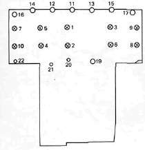
UPPERCASE
1. Engine ground wire 2. Battery ground wire
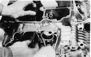
4. Oil pump and strainer cover
a. Place the oil pump drive chain on the transmission main axle.
b. Place the drive chain on the oil pump driven sprocket and install the pump on the crankcase. The "O-ring" should be installed properly.
c. Install the drive chain cover on the oil pump and secure with the 2 shouldered bolts and one normal 6 mm bolt.
Tightening torque: 1.2 m-kg(8.7 ft-lb)
d. Install the strainer cover and torque the bolts to 1.2 m-kg(8.7 ft-lb)
e. Install oil pan (with wire clamps) and torque bolts to 1.2 m-kg(8.7 ft-lb)
1. Wire clamps
Clutch Reassembly
Clutch Reassembly
Clutch assembly
a. Install the thrust plate onto the transmission main axle.
1. Thrust plate
b. Install the oil pump drive sprocket onto the main axle without the spacer collar and place the oil pump drive chain on its sprocket.
1. Oil pump drive sprocket
c. Insert the spacer collar into the oil pump drive sprocket.
1. Spacer collar

(1)Bearing (2)Collar (3)Thrust plate (4)Clutch boss (5)Lock washer (6)Nut
d. Install the primary driven gear (clutch housing) without the bearing and inner spacer.
CAUTION:
Be sure that the oil pump drive gear tabs engage the clutch housing grooves on it's back or the tabs will be damaged when tightening the clutch boss securing nut.
e. Installing the primary driven gear bearing and inner spacer into the clutch housing.
1. Driven gear bearing 2. Inner spacer
f. Install the large thrust plate and clutch boss onto the main axle.
g. Install a new lock washer and nut and tighten the nut to the specified torque. Use the clutch boss holder (special tool).
1. Clutch boss holder
Tightening torque: 7.0 m-kg (50 ft-lb)
h. Bend the lock washer tabs along the nut flats.
1. Lock tab
i. Install the clutch plates without V-cut in tab and friction plates alternately on the clutch boss, starting with a friction plate and ending with clutch plate. Install friction plate wth V-cut (1) last.
NOTE:
Install the friction plate so that the V-cut tab is in the identified dog that was marked during disassembly. If you forgot to identify the position with a mark, measure the width of each dog. The narrow dog is 13.8 mm (0.543 in). All others are 14 mm (0.551 in)
j. Install the plate washer, thrust bearing, and clutch pull rod into the clutch pressure plate from inside.
1. Pull rod 2. Thrust bearing 3. Plate washer
k. Install the pressure plate assembly onto the clutch boss.
NOTE:
Pressure plate has a dot on it which must line up with the dot on clutch boss.
I. Install the clutch springs and screws. Tighten the screws.
Clutch screw torque: 0.8 m-kg (5.8 ft-lb)
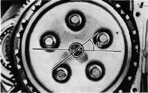
m. Set the gear of the clutch pull rod on the pressure plate facing approximately 45° from horizontal toward the rear; set the clutch lever (if installed) on the right crankcase cover parallel to the gasket surface and install the cover to the crankcase. Do not forget to install two dowel pins.
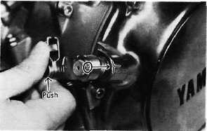
n. If the clutch lever has been removed, install the lever return spring and lever on the shaft after installing the right crankcase cover. In this case make sure that the punch mark on the lever should align with the mark on the crankcase cover when pushing the lever towards the front by hand and then install the circlip.
Middle Gear and Shifter Reassembly
Middle Gear and Shifter Reassembly6. Middle gear (installation only, refer to _tbd__ for the middle gear adjustment)
a. Install the middle drive gear assembly with the proper size of shim(s) and secure it with the bearing retainers and new "TORX" screws.
Tightening torque: 2.5 m-kg (18 ft-lb)
1. Shims
b. Stake the screw heads to the dents on the bearing retainers with a center punch.
c. Install the driven gear assembly with the proper size of shims and secure it with the bolts. Apply a thread locking compound such as "LOCTITE" to the bolt threads,
Tightening torque:
2.5 m-kg (18.1 ft-lb)

1. Shims
d. Install the middle gear case half moon seal onto the crankcase.

1. Seal
7. Shifter assembly
a. Install the shift shaft assembly with the stopper lever.

b. Install the shift lever assembly with the positioning spring is properly located on the stopper pin and the teeth should be set properly as shown.

c. Install the left crankcase cover (shifter cover) using a new gasket. Make sure the wire harness clips are properly positioned.
Tightening torque: 1.0m-kg(7.2ft-lb)
Middle Gear Adjustment
Middle Gear Adjustment
C. Middle Gear Servicing
1. Disassembly
Refer to page 39 for disassembly.
2. Inspection
Refer to page 52 for inspection.
3. Gear lash check
NOTE:
The middle gear lash can be checked only when the gears are installed in the crankcase.
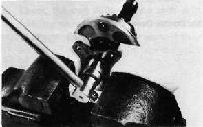
a. Install the middle drive pinion holder (special tool) on the crankcase to hold the drive gear stationary during the lash measurement.
NOTE:
Before installing the tool, loosen the holder bolt all the way out and after installation tighten this bolt as tight as necessary (finder tight is generally sufficient).

1. Middle drive pinion holder
b. Set the dial gauge to the middle drive flange as shown and gently rotate the drive flange back and forth. Note the lash measurement on the dial gauge.

Middle gear lash: 0.1 ~ 0.2mm(0.004~ 0.008 in)
c. Check this engagement at 4 positions. Rotate the drive flange 90° each time and repeat the gear lash check.
NOTE:
If the gear lash exceeds the specified limit and adjustment is necessary, the engine or swing arm should be removed from the motorcycle.
4. Gear lash adjustment
a. Install the driven gear housing assembly into the crankcase leaving about a 2 mm (0.080 in) gap between the housing and crankcase and install the two bolts to the bearing housing 180° opposite to each other.

a. 2 mm (0.080 in)
b. Install the middle drive shaft holder and dial gauge (refer to "Middle gear lash check").
c. Slowly tighten the bolts alternately until the dial gauge lash measurement reaches 0.2 mm (0.008 in).

d. Measure the gap between the driven gear bearing housing flange and the crankcase with a feeler gauge. This is the shim size required.

1. Feeler gauge
e. Install the proper sized shims as shown and tighten the driven gear housing to the specified torque.
Recheck the gear lash, it should be within the specification, if not readjust the shims.
Gear lash: 0.1 - 0.2 mm (0.004-0.008 in
5. Drive gear positioning
NOTE:
When the following part(s) is replaced with new one(s), drive gear positioning is necessary
a. Crankcase
b. Middle gears
c. Middle gear bearing housing
a. Theshim thickness necessary for the drive gear positioning can be calculated from the information found on the upper crankcase and on the drive gear shaft.


b. To find shim thickness "A" use the formula:
A = c —a — b
Where:
a= a numeral (usually a decimal number) printed on the shaft end as shown above and either added to or subtracted from the nominal size "43".
b= a bearing thickness (considered constant)
c = a numeral (usually a decimal number) found on the upper crankcase half near the main bearing selection numbers and added to the nominal size "60".
Distance "b"^ 16.94 mm
Example:
1)lf the shaft is marked +03 ...... "a" is
43.03 mm.
2) "b" is 16.94mm.
3) If thecrankcase is stamped "45" ..... "c"
is 60.45 mm.
A = c — a —b
A = 60.45 -16.94-43.03
A = 0.48
Then the necessary shim thickness is 0.48 mm.
c. Shim size are supplied in the following thicknesses:
0.15 mm, 0.20 mm, 0.30 mm, 0.40 mm, and 0.50 mm.
Because the shims can only be selected in0.05 mm increments the following chart should be used when encountering last digits that are not 5 or zero (0):
|
Last digits |
Rounding |
|
0,1.2 |
0 |
|
3,4,5,6,7 |
5 |
|
8,9 |
10 |
Generator, Starter and Pick-up Coil Reassembly
Generator, Starter and Pick-up Coil Reassembly8. A.C. Generator
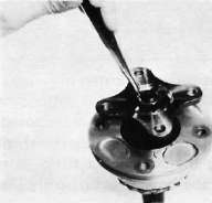
a. Install the rotor onto the shaft and tighten the bolt using the rotor holding tool (special tool) as shown.

1. Rotor holding tool
Tightening torque: 5.5 m-kg (39.8 ft-lb)
b. Install the stator coil assembly onto the crankcase and align the grooves on the stator core with the bolt holes on the crankcase.

c. Install the A.C.G. cover assembly and tighten the bolts to the specification. Do not forget to install the new gasket.
Tightening torque: 1.2 m-kg (8.4 ft-lb)
9. Starter motor
a. Route the A.C.G. lead wires as shown.
b. Install the starter motor and tighten the bolts to the specification.
Tightening torque: 0.7 m-kg (5.1 ft-lb)
NOTE:
Be careful the "O-ring" is not damaged when installing the starter motor.

1. O-ring 2. A.C.G. lead wires
10. Pick-up coil assembly
a. Install the pick-up coil assembly onto the crankcase.
b. Install the timing plate on the crankshaft and tighten the bolt to 0.8 m-kg (5.1 ft-lb)
NOTE:
Note that there is the locating pin on the crankshaft and the corresponding slot in the timing plate which must be aligned to install the timing plate.
Pistons and Cylinder Reassembly
Pistons and Cylinder ReassemblyPistons and Cylinder
a. Install the piston rings onto the pistons. Manufacturer's marks or numbers are located on the top side of the rings.
Install the pistons on the rods. Always use new piston pin clips (1). The arrow on the piston (2) must point to the front of the engine.

NOTE:
Before installing the piston pin clips, cover the crankcase with a clean rag so you will not accidentally drop the circlip into the crankcase. Always install new piston pin circlips.
b. Install the rear chain guide on its pivot. Tighten the holding bolt until it stops and then loosen 1/4 turn and then tighten the lock nut.
1. Holding bolt 2. Rear chain guide
c. Install the new cylinder base gasket and dowel pins. Install the new "O-rings" to the right side dowei pins.
d. Set the crankshaft so that the all pistons are equal height and align the piston rings as shown.
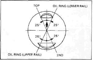
CAUTION:
Make sure the ends of the oil ring expanders are not overlapped.
NOTE:
Manufacturer's marks or numbers stamped on the rings are on the top side of the rings. Coat the pistons and rings well with oil.
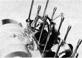
e. Install the piston ring compressors (special tool) and piston bases (special tool). Four piston bases are required.
1. Piston bases 2. Piston ring compressors
f. Tie the cam chain with a piece of mechanic's wire and feed it through the chain opening. Carefully lower the cylinder onto the pistons. Remove the ring compressors and piston bases and repeat this procedure for pistons 1 and 4.
g. Install the cylinder securing nut (front side) and tighten it to the specification.
Tightening torque: 2.0 m-kg (14.5 ft-lb)
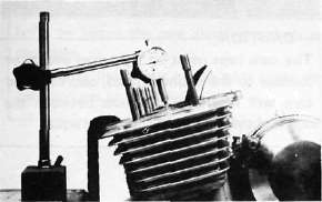
h. Set the dial gauge on the No. 1 piston head center as shown to find the No. 1 piston top dead center and check whether the "1" mark on the timing plate and stationary pointer are aligned or not. If not, loosen the pointer securing screw and adjust.
Cylinder Head and Camshaft Reassembly
Cylinder Head and Camshaft ReassemblyCylinder head and Cam shafts
a. Install the new cylinder head gasket. Install the dowel pins and "O-rings". Locate the cam chain cavity cylinder seal with the tabs down.

b. Install the cylinder head onto the cylinder. Pull the cam chain through the cylinder head as it is installed. Tie the cam chain so that it does not fall into the crankcase.

c. Place the upper cylinder head nuts and washers in place. Follow the illustration for the proper tightening sequence. Torque all nuts in two stages and final torque the upper nuts to the specification.
Tightening torque: 3.5 m-kg (25 ft-lb)
Don't forget the lower nuts on the front and rear of the cylinder head. Torque to the specification.
Tightening torque: 2.0 m-kg (14.5 ft-lb)
a. Copper washers
NOTE:
Tighten the nuts in two stages, 1/2 torque value and then full torque value. Also lubricate the bolt threads with the engine oil to achieve proper torque values.
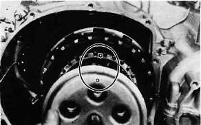
d. Install the front cam chain guide being certain that the lower end is resting in the cam chain guide slot in the crankcase down below.
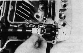
Cam chain sprockets installing steps:
• Align the "T" mark on the timing plate (1) with the stationary pointer on the pickup coil (2). Do not turn the crankshaft when installing the sprockets.

• Place the cam chain onto the exhaust sprocket (3).
• Install the sprockets and finger tighten the sprocket bolts.
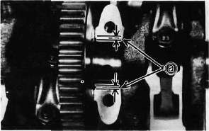
• Rotate the exhaust camshaft to align the punched mark on the camshaft (4) with the arrow on the center cam cap (5).

• Force the exhaust camshaft clockwise to remove the cam chain slack.
• Place the cam chain onto the intake sprocket.
• Install the sprocket and finger tighten the sprocket bolt.
• Rotate the intake camshaft to align the punched mark on the camshaft with the arrow on the center cam cap.
• Force the intake camshaft clockwise to remove all the cam chain slack.

• Insert your finger into the cam chain tensioner hole, and push the cam chain guide inward (6)
• While pushing the cam chain guide, be sure camshaft timing marks align with the cap holes.
• Remove the intake sprocket if marks do not align.
• Change the meshing position of sprocket and cam chain.
• Install the center cam chain guide.

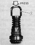
Cam chain tensioner installation steps:
• Remove the tensioner end cap bolt and spring.
• Release the cam chain tensioner one-way cam (1) and push the tensioner rod into the tensioner body.

• Install the tensioner with a new gasket onto the cylinder.
Torque to 1.2 m-kg (8.4 ft-lb)
• Install the tensioner springs and end cap bolt (1). Tighten the bolt to 0.9 m-kg (6.5 ft-lb)

• Turn the crankshaft and install the sprocket securing bolts.
• Tighten the sprocket bolts to 2.0 m-kg (14 ft-lb)
CAUTION:
Be sure to attain the specified torque value to avoid the possibility of these bolts coming loose and causing damage to the engine.

3. Apply engine oil to the cam chain, sprockets, camshafts, and valves.
4. Turn the crankshaft counterclockwise a few turns to ensure that it turns smoothly.
CAUTION:
Be sure the exhaust and intake camshaft marks are aligned with the cam cap marks.
5. Measure:
• Valve clearance
Adjust to specification as described in under Valve Clearance Adjustments:
IN: 0.11 ~ 0.15mm (0.0043 ~ 0.0059 in)
EX: 0.16-0.20 mm (0.0063 ~ 0.0079 in)

6. Install:
Cylinder Head Cover: 1.0 m-kg (7.2ft-lb)
Spark Plug: 20 Nm (2.0 nvkg, 14 ft-lb)

7. Install:
• Gasket
Crankshaft End Cover (Left): 0.7 m-kg, 5.1 ft-lb)
Remounting the Engine
Remounting the EngineREMOUNTING ENGINE
1. Refer to engine removal. Reverse those removal steps that apply.
2. Tighten:
• Engine mount bolts
Engine Mounting Bolt:
Front, upper: 4.2 m-kg (30 ft-lb)
Rear: 9.0 m-kg (65 ft-lb)
Down tube: 3.8 m-kg (27 ft-lb)

3. Connect:
• Pickup coil lead
• Generator lead
• Neutral switch lead
• Oil level switch lead
• Starter motor lead
• Crankcase ventilation hose
• Battery leads
• See CHAPTER 7 "Cable Routing" for proper cable, lead, and hose routing.
• Connect the battery positive lead first.
• Make sure that the cables are not twisted.
• Be careful not to pinch the leads.
4. Install:
• Carburetors
5. Connect:
• Throttle cable
• Choke cable
6. Tighten:
• Air cleaner case mount bolts 1.0 m-kg, (7.2 ft-lb)
7. Install:
• Fuel tank
• Seat
8. Add:
• Engine oil
3.5 L (3.08 Imp qt, 3.70 US qt)