Chapter 2, Periodic Maintenance, Inspections and Adjustments
Chapter 2, Periodic Maintenance, Inspections and AdjustmentsINTRODUCTION
This chapter includes all information necessary to perform recommended inspections and adjustments. These preventive maintenance procedures, if followed, will ensure more reliable vehicle operation and a longer service life. The need for costly overhaul work will be greatly reduced. This information applies to vehicles already in service as well as new vehicles that are being prepared for sale. All service technicians should be familiar with this entire chapter.
Electrical Maintenance
Electrical MaintenanceBATTERY
1. Disconnect:
• Negative lead (1)
• Positive lead (2)
• Breather hose (3)
2. Pull:
• Battery

3. Check:
• Fluid level
Incorrect — Refill.
Fluid level should be between upper (1) and lower (2) level marks.

Refill with distilled water only; tap water contains minerals harmful to a battery.
2. Connect:
• Breather hose
Be sure the hose is properly attached and routed.
3. Inspect:
• Breather hose Obstruction — Remove. Damage — Replace.

HOW TO ROUTE BATTERY BREATHER PIPE.
CAUTION:
Always charge a new battery before using it to ensure maximum performance.
Charging Current: 1.4 amps/10 hrs
Specific Gravity: 1.280 at 20°C(68°F)
Battery electrolyte is dangerous; it contains sulfuric acid and therefore is poisonous and highly caustic. Always follow these preventive measure:
• Avoid bodily contact with electrolyte as it can cause severe burns or permanent eye injury.
• Wear protective eye gear when handling or working near batteries.
Antidote (EXTERNAL):
• SKIN — Flush with water.
• EYES — Flush with water for 15 minutes and get immediate medical attention.
Antidote (INTERNAL):
• Drink large quantities of water or milk follow with milk of magnesia) beaten egg, or vegetable oil. Get immediate medical attention.
Batteries also generate explosive hydrogen gas, therefore, you should always follow these preventive measures:
• Charge batteries in a well-ventilated area.
• Keep batteries away from fire, sparks, or open flames (e.g., welding equipment, lighted cigarettes, etc.)
• DO NOT SMOKE when charging or handling batteries.
KEEP BATTERIES AND ELECTROLYTE OUT OF REACH OF CHILDREN.
HEADLIGHT
Headlight Bulb Replacement
1. Remove:
• Securing screws (1) (from light unit assembly/headlight body.)
2. Disconnect:
• Lead wire

3. Remove:
• Light unit assembly
4. Rotate:
• Bulb holder (1) Turn it counterclockwise.
5. Remove:
• Defective bulb
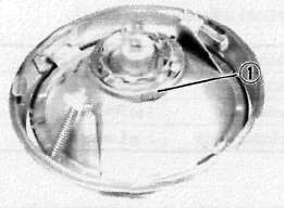
6. Install:
• Bulb (New)
Secure with bulb holder.
• Avoid touching glass part of bulb.
• Keep the bulb free from oil otherwise, transparency of glass, bulb life, and illumi-nous flux will be adversely affected.
• If oil gets on bulb, clean it with a cloth moistened thoroughly with alcohol or lacquer thinner.

Do not touch the headlight bulb when it is on, as the bulb generates enormous heat; keep flammable objects away.
7. Install:
• Light unit assembly (to headlight body.)
Headlight Beam Adjustment
Horizontal adjustment:
1. Rotate:
• Horizontal adjusting screw (1)

|
Horizontal Adjustment of Headlight Beam |
|
|
Adjusting screw |
Beam direction |
|
Turn clockwise |
- to Right |
|
Turn counterclockwise |
- to Left |
Vertical adjustment:
1. Rotate:
• Vertical adjusting screw (2)
|
Vertical Adjustment of Headlight Beam |
|
|
Adjusting screw |
Beam direction |
|
Turn clockwise |
1 to Raise |
|
Turn counterclockwise |
1 to Lower |
FUSE
The fuse box is under the indicator light panel. The main fuse is under the seat.
(1) Main fuse
(2) Other fuse block
(3) Spare fuses


Blown fuse replacement steps.
• Turn off ignition and the circuit.
• Install a new fuse of proper amperage.
• Turn on switches to verify operation of electrical device.
• If fuse blows immediately again, check circuit in question.
Do not use fuses of higher amperage rating than recommended. Extensive electrical system damage and fire could result from substitution of a fuse of improper amperage.
Maintenance Intervals Charts
Maintenance Intervals ChartsProper periodic maintenance is important. Especially important are the maintenance services related to emissions control. These controls not only function to ensure cleaner air but are also vital to proper engine operation and maximum performance. In the following maintenance tables, the services related to emissions control are grouped separately.
PERIODIC MAINTENANCE EMISSION CONTROL SYSTEM
|
ITEM |
REMARKS |
INITIAL ODOMETER READING |
|||||
|
1.000 km (600 mi) or 1 month |
*#1 7.000 km (4.400 mi) or 7 months |
"2 13,000 km (8,200 mi) or 13 months |
19,000 km {12.000 mi) or 19 months |
25,000 km [15,800 mi) or 25 months |
31,000 km <19.600m or 31 months |
||
|
Valve clearance |
Check and adjust valve clearance when engine is cold. |
o |
|||||
|
Spark plug |
Check condition. Adjust gap and clean. Replace at 13,000 km (or 13 months) and thereafter every 12,000 km (or 12 months). |
o |
Replace |
o |
Replace |
o |
|
|
Crankcase ventilation system |
Check ventilation hose for cracks or damage. Replace if necessary. |
o |
o |
o |
|||
|
Fuel line |
Check fuel hose and vacuum pipe for cracks or damage. Replace if necessary. |
|
o |
o |
o |
o |
|
|
Exhaust system |
Check for leakage. Retighten if necessary. Replace gasket(s) if necessary. |
o |
o |
o |
o |
o |
|
|
Idle speed |
Check and adjust engine idle speed. Adjust cable free play. |
o |
o |
o |
o |
o |
|
|
Carburetor synchronization |
Adjust synchronization of carburetors. |
o |
o |
o |
o |
o |
o |
|
•It is recommended that these items be serviced by a Yamaha dealer or other qualified mechanic. |
NOTE:
For farther odometer reading, repeat the above maintenance at the period establish; **1: Every 6.000 km (3,800 mi) "2. Every 12,000 km (7,600 mi) intervals.
GENERAL MAINTENANCE/LUBRICATION
|
No. |
ITEM |
REMARKS |
TYPE |
INITIAL ODOMETER READINGS |
|||||
|
1,000 km (600 mi) or 1 month |
**1 7,000 km (4,400 mi) or 7 months |
**2 13,000 km (8,200 mi) or 13 months |
**3 19,000 km (12,000 mi) or 19 months |
**4 25,000 km (15.800 mi) or 25 months |
31,000 km (19,600 mi or 31 months |
||||
|
1 |
Engine oil |
Warm-up engine before draining. |
See page 12 |
o |
o |
o |
o |
o |
o |
|
2 |
Oil filter |
Replace. |
— |
o |
o |
o |
|||
|
3 |
Air filter |
Clean with compressed air. Replace if necessary. |
— |
o |
o |
o |
o |
o |
|
|
4 |
Brake system |
Adjust free play. Replace pads if necessary. (Front) Replace shoes if necessary (Rear) |
o |
o |
o |
o |
o |
o |
|
|
5 |
Clutch |
Adjust free play. |
— |
o |
o |
o |
o |
o |
o |
|
6 |
Final gear oil |
Check oil level and leakage. Replace every 24,000 km (15,000 mi) or 24 months. |
SAE80 API GL-4 hypoid gear oil |
Replace |
o |
Replace |
|||
|
7 |
Control and meter cable |
Apply chain lube thoroughly. |
Yamaha chain and cable lube or SAE 10W30 motor oil. |
° |
o |
o |
o |
o |
o |
|
8 |
Rear arm pivot shaft |
Check bearings assembly for looseness. Moderately repack every 24,000 km (15,200 mi) |
Medium weight wheel bearing grease |
o |
|||||
|
9 |
Brake/ Clutch ever pivot shaft. |
Apply chain lube lightly. |
Yamaha chain and cable lube or SAE 10W30 motor oil. |
o |
o |
o |
o |
o |
|
|
10 |
Brake pedal and change pedal shaft |
Lubricate Apply chain lube lightly. |
Yamaha chain and cable lube or SAE 10W30 motor oil. |
o |
o |
o |
o |
o |
|
|
11 |
Center/Side stant pivots |
Check operation and lubricate. Apply chain lube lightly. |
Yamaha chain and cable lube or SAE 10W30 motor oil. |
o |
o |
o |
o |
o |
|
|
12 |
Front fork oil |
Check operation and leakage. |
— |
o |
o |
o |
o |
o |
|
|
13 |
Steering bearings |
Check bearings assembly for looseness. Moderately repack every 24,000 km (15,000 mi) |
Medium weight wheel bearing grease |
O |
o |
o |
o |
o |
|
|
14 |
Wheel bearings |
Check bearings for smooth rotation. |
— |
o |
o |
O |
o |
o |
|
|
15 |
Battery |
Check specific gravity and breather pipe for proper operation. |
— |
o |
o |
o |
o |
o |
|
|
16 |
A.C. Generator |
Replace generator brushes. |
o |
o |
|||||
|
17 |
Sidestand switch |
Check and clean or replace if necessary. |
O |
o |
o |
o |
o |
o |
|
■ it is recommended that these items be serviced by a Yamaha Dealer or other qualified mechanic.
NOTE:
For greater odometer readings repeat the above maintenance at the period established, IE: **1: Every 6,000 km (3,800 mi), **2: Every 12,000 km (7,600 mi), **3: Every 18,000 km (11,400 mi), **4: Every, 24,000 km (15,200 mi) intervals.
Engine
EngineContents of Engine Maintenance:
Valve Adjustments
Valve AdjustmentsVALVE CLEARANCE ADJUSTMENT
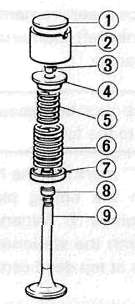
(1)Pad (2) Valve lifter (3) Valve retainer (4)Spring seat (5)inner spring (6) Outer spring (7) Spring seat (8) Oil seal (9) Valve
|
A |
VALVE CLEARANCE (COLD): |
|
|
B |
Intake: |
0.11 -0.15 mm (0.0043-0.0059 in) |
|
C |
Exhaust: |
0.16-0.20 mm (0.0063-0.0079 in) |
Removal
1. Remove:
• Seat
• Fuel tank
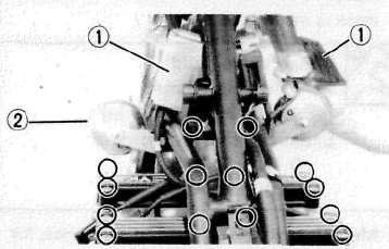
• Ignition coil covers (1)
• Horns with stay (2)
2. Disconnect:
• Spark plug caps
3. Remove:
• Spark plugs
• Cylinder head cover
4. Remove:
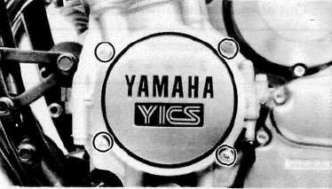
• Emblem plate (Left)
Inspection and Adjustment
1. Measure:
• Valve clearance
NOTE:
Be sure piston is at Top Dead Center (TDC) on compression stroke when measuring clearance.
Valve clearance measurement steps:
• Turn the crankshaft counterclockwise with a 19 mm spanner (1) .
NOTE:
Valve clearance must be measured when the engine is cool to the touch.
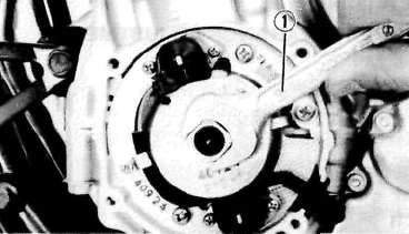
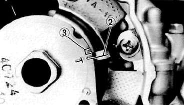
• Align the "T" mark (for the No. 1 or No. 4 cylinder) on the timing plate with the stationary pointer (2). When the "T" mark is aligned with the stationary pointer (2), the piston is at top dead center TDC.
(3) Firing range for No. 1 cylinder
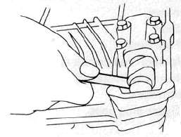
• Measure the valve clearance using a Feeler Gauge.
• Record the measured amount if the clearance is incorrect.
Intake Valve (cold): 0.11 —0.15 mm (0.0043 ~ 0.0059 in)
Exhaust Valve (cold): 0.16 —0.20 mm (0.0063 ~ 0.0079 in)
• Measure valve clearance, in sequence, for Nos. 2, 4, and No. 3 cylinders. Out of specification — Adjust clearance.
Firing Sequence: 1-2-4-3
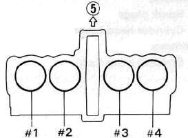
(5) Front
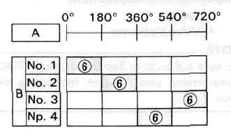
A Crankshaft counterclockwise turning angle.
B Cylinder
(6) Combustion
2. Adjust:
• Valve clearance
Valve clearance adjustment steps:
• Position the valve lifter slots (intake and exhaust) opposite each other.
• Turn the camshaft until the lobe fully depresses the valve lifter and opens the valve.
• Attach the Tappet Adjusting Tool (1) (YM-01245) onto the cylinder head.
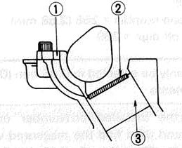
NOTE:
Make sure that the tool contacts the lifter (3) only, and not the pad (2).
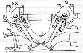
• Carefully rotate the camshaft so that the pads can be removed. To avoid cam touching the adjusting tool, turn cams as shown.
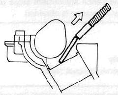
Intake: Carefully rotate CLOCKWISE. Exhaust: Carefully rotate COUNTERCLOCKWISE.
• Remove the pads (2) from the lifters. Use a small screwdriver and a magnetic rod for removal.Note pad numbers.
• Select the proper valve adjusting pad from the chart below:
|
Pad range |
Pad Availability: 25 increments |
|
No. 200 - 2.00mm (0.079 in) |
Pad stepped in 0.05 mm (0.002 in) increments |
NOTE:
Thickness of each pad is marked on the pad face that contacts the valve lifter (not the cam).
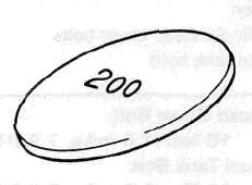
• Round off the hundredths digit of the original pad number to the nearest 0.05 mm increment.
|
Hundredths digit |
Rounded valve |
|
0 or 2 |
0 |
|
5 |
NOT ROUNDED OFF |
|
8 |
10 |
EXAMPLE:
Original pad number = 258 (2.58 mm)
Rounded off digit = 260
NOTE:
Pad can only be selected in 0.05 mm (0.002 in) increments.
Determine the required replacement pad thickness by one of the two following methods:
Shim calculation method:
Since all shims come in .05mm (.002") increments, you can quickly calculate the required size without a chart.
If the measured clearance is within 0.05mm (0.002") of the required clearance, then no change is needed.
If the measured clearance greater than 0.05mm (0.002") but 0.10mm (0.004") or less different than the required clearance then the next size shim is required.
If the measured clearance greater than 0.10mm (0.004") but 0.15mm (0.006") or less different than the required clearance then the next size shim is required.
Clearances that are too small require thinner shims. Clearances that are too large require thicker shims.
Example: Required exhaust valve clearance is 0.16~0.20mm. Measured clearance is 0.12mm (gap too small). Installed shim is Y270. Required shim is one size thinner: Y265.
Shim Chart Lookup Method:
• Locate the "Installed Pad Number" on the chart, and then find the measured valve clearance. The point where these coordinates intersect is the new pad number.
NOTE:
Use the new pad number as a guide only as the number must be verified.
Pad number verification steps:
• Install the new pad with the number down.
• Remove the adjusting tool.
• Recheck the valve clearance.
• If the clearance is incorrect, repeat all of the clearance adjustment steps until the proper clearance is obtained.
Assembly
1. Reverse removal steps.
NOTE:
Inspect the head cover gasket and replace it if damaged.
2. Tighten:
• Cylinder head cover bolts
• Fuel tank bolts
Head Cover Bolt:
10Nm(1.0mkg, 7.2 ftlb)
Fuel Tank Bolt:
10Nm(1.0rrvkg, 7.2 ftlb)
INTAKE
|
MEASURED |
INSTALLED PAD NUMBER |
||||||||||||||||||||||||
|
200 |
205 |
210 |
215 |
220 |
225 |
230 |
235 |
240 |
245 |
250 |
255 |
260 |
265 |
270 |
275 |
280 |
285 |
290 |
295 |
300 |
305 |
310 |
315 |
320 |
|
|
0.00 - 0 05 |
200 |
205 |
210 |
215 |
220 |
225 |
230 |
235 |
240 |
245 |
250 |
255 |
260 |
265 |
270 |
275 |
280 |
285 |
290 |
295 |
300 |
305 |
310 |
||
|
0.06 - 0 10 |
200 |
205 |
210 |
215 |
220 |
225 |
230 |
235 |
240 |
240 |
260 |
255 |
260 |
265 |
270 |
275 |
280 |
285 |
290 |
295 |
300 |
305 |
310 |
315 |
|
|
0 11 - 0.15 |
|||||||||||||||||||||||||
|
0 16 - 0.20 |
205 |
210 |
215 |
220 |
225 |
230 |
235 |
240 |
245 |
250 |
255 |
260 |
265 |
270 |
275 |
280 |
285 |
290 |
295 |
300 |
305 |
310 |
315 |
320 |
|
|
0.21 - 0.25 |
210 |
215 |
220 |
225 |
230 |
235 |
240 |
245 |
250 |
255 |
200 |
265 |
270 |
275 |
280 |
285 |
290 |
295 |
300 |
305 |
310 |
315 |
320 |
||
|
0 26 - 0.30 |
215 |
220 |
225 |
230 |
235 |
240 |
245 |
250 |
255 |
260 |
265 |
270 |
275 |
280 |
285 |
290 |
295 |
300 |
305 |
310 |
315 |
320 |
|||
|
0.31 - 0.35 |
220 |
22ft |
230 |
23ft |
240 |
245 |
250 |
255 |
260 |
265 |
270 |
275 |
280 |
285 |
290 |
295 |
300 |
305 |
310 |
315 |
320 |
||||
|
0 36 - 0 40 |
225 |
230 |
235 |
240 |
245 |
250 |
255 |
260 |
265 |
270 |
275 |
280 |
285 |
290 |
295 |
300 |
305 |
310 |
315 |
320 |
|||||
|
0 41 - 0 45 |
230 |
235 |
240 |
245 |
250 |
255 |
260 |
265 |
270 |
275 |
280 |
285 |
290 |
295 |
300 |
305 |
310 |
315 |
320 |
||||||
|
0.46 - 0 50 |
235 |
240 |
245 |
250 |
255 |
260 |
265 |
270 |
275 |
280 |
285 |
290 |
295 |
300 |
305 |
310 |
315 |
320 |
|||||||
|
0 51 - 0.55 |
240 |
245 |
250 |
255 |
260 |
265 |
270 |
275 |
280 |
285 |
290 |
295 |
300 |
305 |
310 |
315 |
320 |
||||||||
|
0 56 - 0 60 |
245 |
250 |
255 |
260 |
265 |
270 |
275 |
280 |
285 |
290 |
295 |
300 |
305 |
310 |
315 |
320 |
|||||||||
|
0.61 - 0.65 |
250 |
255 |
260 |
265 |
270 |
275 |
280 |
285 |
290 |
295 |
300 |
305 |
310 |
315 |
320 |
||||||||||
|
0 66 - 0.70 |
255 |
260 |
265 |
270 |
275 |
280 |
285 |
290 |
295 |
300 |
305 |
310 |
315 |
320 |
|||||||||||
|
0.71 - 0.75 |
260 |
265 |
270 |
275 |
280 |
285 |
290 |
295 |
300 |
305 |
310 |
315 |
320 |
||||||||||||
|
0.76 - 0 80 |
265 |
270 |
275 |
280 |
285 |
290 |
295 |
300 |
305 |
310 |
315 |
320 |
|
||||||||||||
|
0.81 - 0.85 |
270 |
275 |
280 |
285 |
290 |
295 |
300 |
305 |
310 |
315 |
320 |
||||||||||||||
|
0 86 - 0 90 |
275 |
280 |
285 |
290 |
295 |
300 |
305 |
310 |
315 |
320 |
VALVE CLEARANCE (cold): |
||||||||||||||
|
0.91 - 0.95 |
280 |
285 |
290 |
295 |
300 |
305 |
310 |
315 |
320 |
||||||||||||||||
|
0.96 - 1 00 |
285 |
290 |
295 |
300 |
305 |
310 |
315 |
320 |
0.11 to 0.15 mm (0.004 — 0.006 in) |
||||||||||||||||
|
1.01 - 1.05 |
290 |
295 |
300 |
305 |
310 |
315 |
320 |
||||||||||||||||||
|
1.06 - 1.10 |
295 |
300 |
305 |
310 |
315 |
320 |
Measured clearance is 0.32 mm (0.013 in) |
||||||||||||||||||
|
1.11 - 1.15 |
300 |
305 |
310 |
315 |
320 |
||||||||||||||||||||
|
1.16 - 1.20 |
305 |
310 |
315 |
320 |
Pad number : (example) |
||||||||||||||||||||
|
1 21 - 1 25 |
310 |
315 |
320 |
||||||||||||||||||||||
|
1 26 - 1 30 |
315 |
320 |
Pad No. 255 = 2.55 mm (0.100 in) |
||||||||||||||||||||||
|
1.31 - 1 35 |
320 |
||||||||||||||||||||||||
EXHAUST
|
MEASURED |
INSTALLED PAD NUMBER |
||||||||||||||||||||||||
|
200 |
205 |
210 |
215 |
220 |
225 |
230 |
235 |
240 |
245 |
250 |
255 |
260 |
265 |
270 |
275 |
280 |
285 |
290 |
295 |
300 |
305 |
310 |
315 |
320 |
|
| 0.00 - 0 05 |
200 |
205 |
210 |
215 |
220 |
225 |
230 |
235 |
240 |
245 |
250 |
255 |
260 |
265 |
270 |
275 |
280 |
285 |
290 |
295 |
300 |
305 |
|||
|
0.06 - 0 10 |
200 |
205 |
210 |
216 |
220 |
225 |
230 |
235 |
240 |
245 |
250 |
255 |
260 |
265 |
270 |
275 |
280 |
285 |
290 |
295 |
300 |
305 |
310 |
||
|
0 11 - 0.15 |
200 |
205 |
210 |
215 |
220 |
225 |
230 |
235 |
240 |
245 |
250 |
255 |
260 |
265 |
270 |
275 |
280 |
285 |
290 |
295 |
300 |
305 |
310 |
315 |
|
|
0 16 - 0.20 |
|||||||||||||||||||||||||
|
0.21 - 0.25 |
205 |
210 |
215 |
220 |
225 |
230 |
235 |
240 |
246 |
250 |
255 |
260 |
265 |
270 |
275 |
280 |
285 |
290 |
295 |
300 |
305 |
310 |
315 |
320 |
|
|
0 26 - 0.30 |
210 |
215 |
220 |
225 |
230 |
235 |
240 |
245 |
250 |
255 |
260 |
265 |
270 |
275 |
280 |
285 |
290 |
295 |
300 |
305 |
310 |
315 |
320 |
||
|
0.31 - 0.35 |
216 |
220 |
225 |
230 |
235 |
240 |
24ft |
260 |
255 |
2ft0 |
20ft |
270 |
275 |
280 |
285 |
290 |
295 |
300 |
305 |
310 |
315 |
320 |
|||
|
0 36 - 0 40 |
220 |
225 |
230 |
235 |
240 |
245 |
250 |
255 |
260 |
265 |
270 |
275 |
280 |
285 |
290 |
295 |
300 |
305 |
310 |
315 |
320 |
||||
|
0 41 - 0 45 |
225 |
230 |
235 |
240 |
245 |
250 |
255 |
260 |
265 |
^70 |
2'5 |
280 |
285 |
290 |
295 |
300 |
305 |
310 |
315 |
320 |
|||||
|
0.46 - 0 50 |
230 |
235 |
240 |
245 |
250 |
255 |
260 |
265 |
270 |
275 |
280 |
285 |
290 |
295 |
300 |
305 |
310 |
315 |
320 |
|
|||||
|
0 51 - 0.55 |
235 |
240 |
245 |
250 |
255 |
260 |
265 |
270 |
275 |
280 |
285 |
290 |
295 |
300 |
305 |
310 |
315 |
320 |
|||||||
|
0 56 - 0 60 |
240 |
245 |
250 |
255 |
260 |
265 |
270 |
275 |
280 |
285 |
290 |
295 |
300 |
305 |
310 |
315 |
320 |
||||||||
|
0.61 - 0.65 |
245 |
250 |
265 |
260 |
265 |
270 |
275 |
280 |
285 |
290 |
295 |
300 |
305 |
310 |
315 |
320 |
|||||||||
|
0 66 - 0.70 |
250 |
255 |
260 |
265 |
270 |
275 |
280 |
285 |
290 |
295 |
300 |
305 |
310 |
315 |
320 |
||||||||||
|
0.71 - 0.75 |
255 |
260 |
265 |
270 |
275 |
280 |
285 |
290 |
295 |
300 |
305 |
310 |
315 |
320 |
|||||||||||
|
0.76 - 0 80 |
260 |
265 |
270 |
275 |
280 |
285 |
290 |
295 |
300 |
305 |
310 |
315 |
320 |
||||||||||||
|
0.81 - 0.85 |
265 |
2 70 |
275 |
280 |
285 |
290 |
295 |
300 |
306 |
310 |
315 |
320 |
|||||||||||||
|
0 86 - 0 90 |
270 |
275 |
280 |
285 |
290 |
295 |
300 |
305 |
310 |
316 |
320 |
VALVE CLEARANCE (cold): |
|||||||||||||
|
0.91 - 0.95 |
276 |
280 |
285 |
290 |
295 |
300 |
305 |
310 |
316 |
320 |
|||||||||||||||
|
0.96 - 1 00 |
280 |
285 |
290 |
295 |
300 |
305 |
310 |
315 |
320 |
0.16 - 0.20 mm (0.006 - 0.008 in) |
|||||||||||||||
|
1.01 - 1.05 |
285 |
290 |
295 |
300 |
305 |
310 |
315 |
320 |
|||||||||||||||||
|
1.06 - 1. 10 |
290 |
295 |
300 |
305 |
310 |
315 |
320 |
Measured clearance is 0.32 mm (0.013 in) |
|||||||||||||||||
|
1. 11 - 1. 15 |
295 |
300 |
305 |
310 |
315 |
320 |
|||||||||||||||||||
|
1. 16 - 1. 20 |
300 |
305 |
310 |
315 |
320 |
Pad number : (example) |
|||||||||||||||||||
|
1 21 - 1 25 |
305 |
310 |
315 |
320 |
|||||||||||||||||||||
|
1 26 - 1 30 |
310 |
315 |
320 |
Pad No. 255 = 2.55 mm (0.100 in) |
|||||||||||||||||||||
|
1.31 - 1 35 |
320 |
||||||||||||||||||||||||
Spark Plug, Emmissions, Exhaust and Carburetor
Spark Plug, Emmissions, Exhaust and Carburetor
SPARK PLUG
1. Remove:
• Spark plug(s)
2. Inspect:
• Electrode (1) Wear/Damage — Replace.
• Insulator color (2)
3. Measure:
• Plug gap (3)
Use a Wire Gauge or Feeler Gauge. Out of specification — Regap.
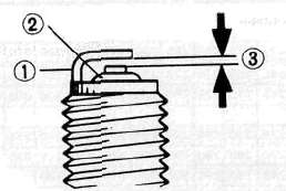
0.7 ~ 0.8 mm (0.028 - 0.31 in)
Clean the plug with a spark plug cleaner if necessary-
Standard Spark Plug: BP8 ES (NGK) W24EP-U (NIPPONDENSO)
Before installing a spark plug, clean the gasket surface and plug surface.
4. Tighten:
• Spark plug(s)
20 Nm (2.0 mkg, 14ftlb)
NOTE:
Finger-tighten the spark plug(s) before torquing to specification.
CANISTER (For California Only)
This model is equipped with a canister to prevent the discharging of fuel vapor into the atmosphere.
1. Inspect:
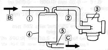
• Hoses (1) (2) (5) Cracks/Damage — Replace. Clog - Clean.
• Canister (4) Cracks/Damage — Replace.
3 Carburetor [B] From fuel tank [C] To atmosphere
A EMISSION HOSE ROUTING
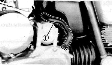
CRANKCASE VENTILATION SYSTEM
1. Inspect:
• Crankcase ventilation hose ® Cracks/Damage — Replace.
FUEL LINE
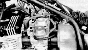
1. Inspect:
• Fuel hose (1)
• Vacuum hose (2) Cracks/Damage — Replace.
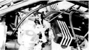
INTAKE MANIFOLD
1. Tighten:
• Carburetor clamps
• Carburetor joint bolts
2. Inspect:
• Carburetor joint
• Gaskets Cracks/Damage — Replace.
EXHAUST SYSTEM
1. Inspect:
• Exhaust pipe gasket(s) (1)
• Muffler clamp gasket(s) (2) Damage — Replace. Exhaust gas leakage — Repair.
2. Tighten:
• Exhaust pipe bolts
• Muffler bolts
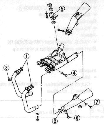
Exhaust Pipe Flange (3) :
10 Nm (1.0 m-kg, 7.2ft-lb)
Exhaust Pipe Clamp (4) :
20 Nm (2.0 m-kg, 14ftlb)
Muffler Bracket (5) :
25 Nm (2.5 m-kg, 18 ft-lb)
Exhaust Chamber Mount (7) :
20 Nm (2.0 m-kg, 14 ft-lb)
Muffler Clamp (6) :
20 Nm (2.0 m-kg, 1 4 ft-lb)
IDLE SPEED/CARBURETOR SYNCHRONIZATION
IDLE SPEED
1. Adjust
• Idle speed
Warm up the engine and turn the throttle stop screw (1) to adjust.
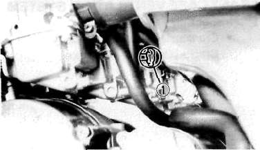
Idle Speed
1,050 + 50 r/min
Carburetor Adjustment.
Carburetors must be adjusted to open and close simultaneously.
NOTE:
Valve clearance must be set properly before synchronizing the carburetors.
1. Remove:
• Seat
• Fuel tank
2. Disconnect:
• Vacuum plugs (1)
• Vacuum hose (2)
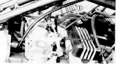
3. Install:
• Vacuum Gauge (YU-08030) (1)
• Suitable test fuel tank
4. Remove:
• Y.I.C.S. plug (2)
5. Attach:
• Y.I.C.S. shutoff tool (YM-08025) (3)
6. Start the engine and let it warm up.
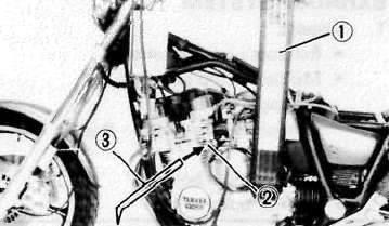
7. Inspect:
• Idle speed
Out of specification — Turn throttle stop screw (1) to adjust.
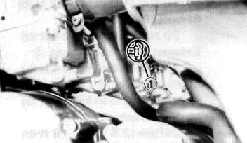
Idle Speed
1,050 ±50 r/min
8. Adjust:
• Carburetor synchronization
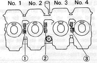
Carburetor synchronization adjustment steps:
• Synchronize the carburetor No. 1 to the carburetor No. 2 by turning the synchronizing screw (1) until the both gauge readings are the same.
• Rev. the engine for a fraction of a second, two or three times, and check the synchronization again.
Vacuum Pressure at Idle Speed:
23.99 kPa (180 mm Hg, 7.09 in Hg)
Vacuum Synchronous Difference:
0.67 kPa (5 mm Hg, 0.2 in Hg)
• Repeat the above steps to synchronize the carburetor No. 4 to the carburetor No. 3 by turning the synchronizing screw (3) until the both gauge readings are the same.
• Repeat the same steps to synchronize No. 3 carburetor to No. 1 carburetor, then turn synchronizing screw (2) until both gauge readings are the same.
Engine Oil
Engine Oil
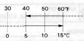
At 5°C (40°F) or Higher:
SAE 20W40 Type SE Motor Oil
At 15°C (60°F) or Lower:
SAE 10W30 Type SE Motor Oil
NOTE:
Recommended engine oil classification; API Service "SE", "SF" type or equivalent (e.g. "SF-SE", "SF-SE-CC", "SF-SE-SD" etc.)
Oil Level Measurement
1. Check
• Oil level
Oil level low — Add sufficient oil.
Oil level visual inspection steps:
• Place the motorcycle on its center stand and warm up the engine for several minutes.
NOTE:
Position the motorcycle straight up when checking oil level, a slight tilt to the side can produce false readings.
• Stop the engine and visually check the oil level through the level window (1).
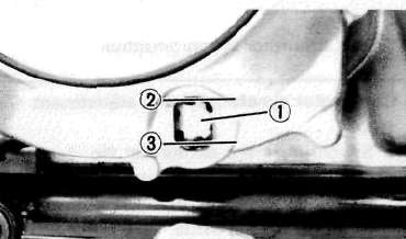
(2) Maximum (3) Minimum
Oil Change (Without filter)
1. Warm up the engine for several minutes, then place a receptacle under the engine.
2. Remove:
• Oil filler cap
3. Remove:
• Engine drain plug (1)
4. Tighten:
• Drain plug
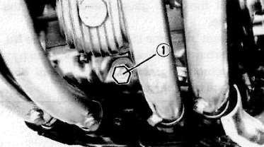
Engine Drain Plug:
43 Nm (4.3 m-kg, 31 ft-lb)
5. Fill:
• Crankcase
Engine Oil
2.5 L (2.2 imp qt, 2.6 US qt)
CAUTION:
Do not allow foreign material to enter the crankcase.
6. Install:
• Filler cap
Oil Change (With filter)
1. Warm up the engine and place a receptacle under the engine.
2. Remove:
• Oil filler cap
• Drain plug
Drain the engine oil.
3. Remove:
• Oil filter bolt (1)
• Filter cover (2)
4. Tighten:
• Drain plug
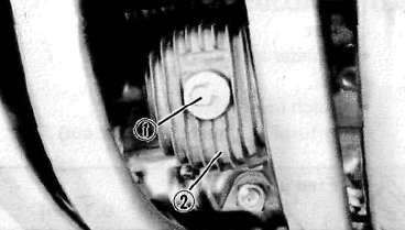
Engine Drain Plug:
43 Nm (4.3 m-kg, 31 ft-lb)
5. Install:
• Oil filter bolt (1)
• Spring (2)
• Washer (3)
• Oil filter (New) (4)
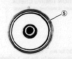
• O-ring (5)
• Oil filter assembly
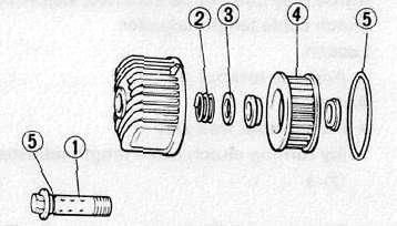
• Be sure the O-ring (5) is positioned properly.
• Fit the filter cover projection into the crank-case cover slot.
6. Tighten:
• Oil filter bolt
Oil Filter Bolt:
15 Nm (1.5 mkg, 11 ftlb)
7. Fill:
• Crankcase
Engine Oil:
2.8 L (2,5 imp qt, 3.0 US qt)
8. Install:
• Oil filler cap
9. Warm up the engine and check for oil leaks. Stop the engine instantly if leaking occurs.
Leaks — Check cause.
10. Check:
• Oil level
Level low — Add sufficient oil.
Clutch, Timing and Compression
Clutch, Timing and CompressionCLUTCH ADJUSTMENT
1. Loosen:
• Adjuster locknut (1)
2. Adjust:
• Clutch lever free play (3)
(by turning adjuster (2) in or out)
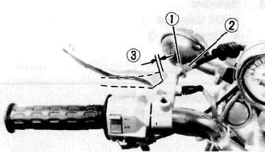
Free play:
2-3 mm (0.08 - 0.12 in)
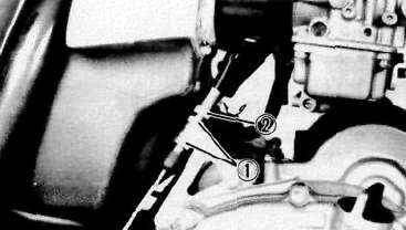
If free play can not be adjusted, adjust by clutch cable length adjuster.
3. Loosen:
• Adjuster locknut (1)
4. Adjust:
• Clutch lever free play
(by turning clutch cable length adjuster (2) )
IGNITION TIMING CHECK
Flywheel is marked as follows:
(1) TDC for No. 1 cylinder
(2) Firing range for the No. 1 cylinder
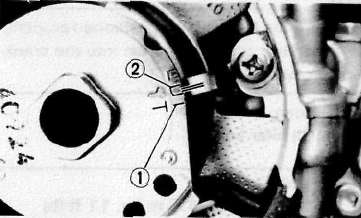
1. Check:
• Ignition timing
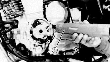
Ignition timing check steps:
• Remove the cover.
• Connect the Timing Light (YM-33277) i to No. 1 cylinder spark plug lead.
• Warm up the engine and let it idle at the specified idle speed of 1,050 ± 50 r/min.
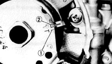
• Visually check the stationary pointer in the timing window to verify it is within the required firing range indicated on the flywheel.
Incorrect firing — Check timing plate and/or pickup assembly (tightness damage)
Refer to CHAPTER 6, "ELECTRICAL" for further information.
(1) TDC for No. 1 cylinder
(2) Firing range for the No. 1 cylinder
COMPRESSION PRESSURE MEASUREMENT
NOTE:
Insufficient compression pressure will result in performance loss.
1. Measure:
• Valve clearance
Out of specification — Adjust.
2. Warm up the engine.
3. Remove:
• Spark plugs
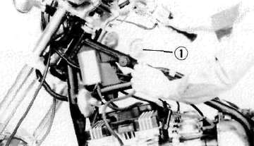
Compression pressure measurement steps:
• Install the Compression Gauge (YU-33223) (1) using an adapter.
• Crank over the engine with the electric starter (be sure the battery is fully charged) with the throttle wide-open until the compression reading on the gauge stabilizes.
• Check readings with specified levels (See chart).
Compression Pressure (at sea level):
Standard: 1,078 kPa (11 kg/cm2, 156 psi)
Minimum: 882 kPa (9 kg/cm2, 128 psi)
Maximum: 1,176 kPa (12 kg/cm2, 171 psi)
When cranking the engine, ground all of the spark plug leads to prevent sparking.
• Repeat the previous steps for the other cylinders.
• If pressure falls below the minimum level:
1. Squirt a few drops of oil into the affected cylinder.
2. Measure the compression again.
|
Compression Pressure (with oil introduced into cylinder) |
|
|
Higher than without oil |
Worn or damaged pistons |
|
Same as without oil |
Defective ring(s). valves, cylinder head gasket or piston is possible. |
|
Above maximum level |
Inspect cylinder head, valve surfaces, or piston crown for carbon deposits. |
NOTE:
The difference between the highest and lowest cylinder compression readings must not vary more than the specified value.
Difference Between Each Cylinder:
Less than 98 kPa (1 kg/cm2,14 psi)
Chassis Maintenance
Chassis Maintenance
FINAL GEAR OIL
Oil Level Measurement
1. Place the motorcycle on a level area and place on its centerstand.
2 Remove:
• Oil filler cap
3. Observe:
• Oil level (2)
Low level— Add oil. (1) Oil
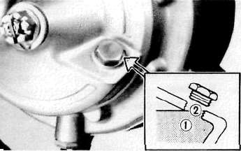
NOTE:
Oil level must be up to the brim of the filler hole.
CAUTION:
Be sure that no foreign material enters the final gear case.
Gear Oil Replacement
1. Place a receptacle under the final gear case.
2. Remove:
• Filler cap
• Drain plug (1) Drain final gear oil.
3. Install:
• Drain plug
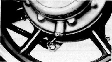
23 Nm (2.3 m-kg, 17ftlb)
4. Fill
• Gear case (to specified level.)
Final Gear oil:
SAE80 API "GL-4" Hypoid
gear oil Oil Capacity:
0.20 / (0.18 imp qt, 0.21 qt)
NOTE:
If desired, an SAE 80W90 Hypoid gear oil may be used for all conditions.
5. Install:
• Filler cap
23 Nm (2.3 m-kg, 17 ft-lb)
AIR FILTER
1. Remove:
• Seat
• Fuel tank
• Rubber cover
2. Remove:
• Air filter cover (1)
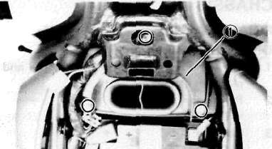
3. Eliminate:
• Dust
Use compressed air
4. Inspect:
• Element Damage - Replace.
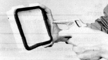
CAUTION:
The engine should never be run without the air/filter element installed; excessive piston and/or cylinder wear may result.
5. Install:
• Element
CAUTION:
Make sure the element cover fits into the corresponding filter case edge.
FRONT BRAKE
Brake Fluid Inspection
1. Check:
• Brake fluid level
Level low — Replenish.
NOTE:
Use only a designated, quality fluid.
DOT NO. 3
NOTE:
Be sure that:
• Water does not enter the master cylinder when refilling.
• Spilled fluid is cleaned up immediately to prevent painted surfaces or plastic parts from eroding.
(1) Lower level
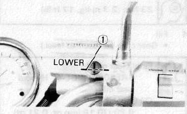
FRONT BRAKE/REAR BRAKE
Front Brake Lever Free Play Adjustment
1. Loosen:
• Adjuster lockout (1)
2. Adjust:
• Free play (3)
Turn the adjuster (2) until the free play (3) is within the specified limits.
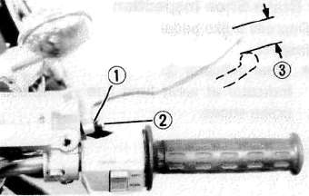
Brake Lever Free Play:
2-5 mm (0.08 ~ 0.2 in)
CAUTION:
Proper level free play is essential to avoid excessive brake drag.
3. Tighten:
• Adjuster locknut
Brake Pad Inspection
1. Activate the brake lever
2. Inspect:
• Wear indicator (1) Indicator almost contacts disc (2) — Replace pads. Refer to CHAPTER 5, "CHASSIS."
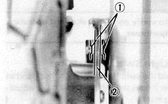
REAR BRAKE
Rear Brake Pedal Height Adjustment
1. Loosen:
• Adjust locknut (1) .
2. Adjust:
• Brake pedal height (2).
Turn the adjuster (3) until the brake pedal position is at the specified height.
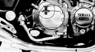
Brake Pedal Height: 10 mm (0.4 in) Below the Top of the Footrest
Adjust pedal height, then adjust brake pedal free play.
REAR BRAKE
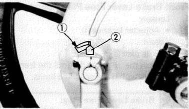
Rear Brake Shoe Inspection
1. Depress brake pedal
2. Inspect:
• Wear indicator (2)
Indicator at wear limit line — Replace brake shoes.
(1) Wear limit line
Rear Brake Pedal Free Play Adjustment
1. Rotate:
• Adjuster nut (1)
Turn it clockwise or counterclockwise until proper brake pedal free play is attained.
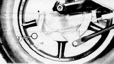
Brake Pedal Free Play:
20-30 mm (0.8 -1.2 in)
Check to verify correct brake light operation after adjustment.
Brake Light Switch Adjustment
1. Hold the switch body (1) with your hand so that it does not rotate and turn the adjusting nut (2) .
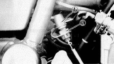
CABLE INSPECTION AND LUBRICATION
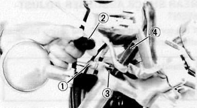
Cable inspection and lubrication steps:
• Remove the two screws that secure throttle housing to handlebar.
• Hold cable end high and apply several drops of lubricant to cable.
• Coat metal surface of disassembled throttle twist grip with suitable all-purpose grease to minimize friction.
• Check for damage to cable insulation. Replace any corroded or obstructed cables.
• Lubricate any cables that do not operate smoothly.
SAE 10W30 Motor Oil
BRAKE AND CHANGE PEDALS/ BRAKE CLUTCH LEVERS
Lubricate pivoting parts of each lever and pedal.
CENTERSTAND AND SIDESTAND
Lubricate centerstand and sidestand at their pivot points.
SAE 10W30 Motor Oil
FRONT FORK OIL CHANGE
Securely support the motorcycle so there is no danger of it falling over.
1. Place a suitable stand under the engine to raise the front wheel off the ground.
2. Loosen:
• Inner tube pinch bolt (1)
3. Remove:
• Fork cap (2)
• Cap bolt (3)
Use the Front Fork Cap Socket (YM-01104) (4)
4. Remove:
• Drain screw (1) Drain the fork oil.
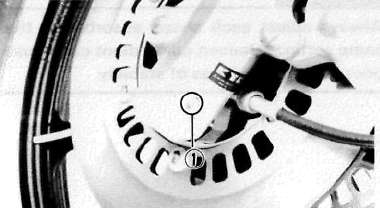
Do not allow any oil to contact the disc brake components. If oil is discovered, be sure to remove it, otherwise diminished braking capacity and damage to the rubber components of the brake assembly will occur.
7. Inspect:
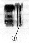
• O-ring (1) (Cap-bolt)
• Gasket (Drain screw) Wear/Damage — Replace.
8. Install:
• Drain screw
9. Fill:
• Front fork
Each Fork:
383cm3(13.51 impoz, 12.95 USoz)
After filling pump the forks slowly up and down to distribute the oil.
10. Tighten:
• Cap-bolt
• Pinch bolt
Cap Bolt: 23 Nm (2.3 rrvkg, 17ftlb)
Pinch Bolt: 20 Nm (2.0 mkg, 14ft-lb)
11. Install:
• Fork cap
REAR SHOCK ABSORBER ADJUSTMENT
If the spring seat is raised, the spring becomes stiffer, and if lowered, it becomes softer.
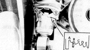
Standard Position: B A. — Softest (1) E. — Stiffest (2)
Always adjust each shock absorber to the same setting. Uneven adjustment can cause poor handling and loss of stability.
STEERING HEAD ADJUSTMENT
Steering Head Inspection
1. Place the motorcycle on its centerstand, then elevate the front wheel.
2. Check:
• Steering assembly bearings
Grasp the bottom of the forks and gently rock the fork assembly back and forth. Looseness — Adjust.
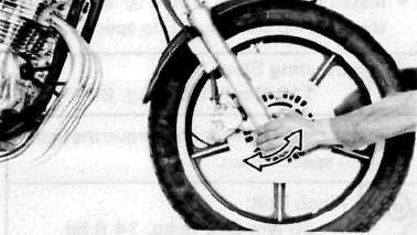
Adjustment
Steering head adjustment steps:
• Remove the handlebar securing bolts (1)
• Remove the handlebars .
• Remove the steering stem nut (2)
• Loosen the pinch bolts (3) .
• Remove the steering crown (4) .
• Remove the lock washer (5) .
• Loosen the ring nut (6) ,
• Tighten the ring nut (7) .
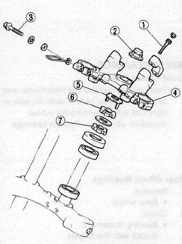
Ring Nut (Lower):
50 Nm (5.0 m-kg, 36 ft-lb)
The tapered side of ring nuts must face downward.
• Loosen the ring nut (7) completely and retighten it to specification.
Ring Nut (Lower):
6Nm(0.6 m-kg,4.3ft-lb)
• Check the steering stem by turning it lock to lock. If there is any binding, remove the steering stem assembly and inspect the steering bearings 8 .
(See CHAPTER 5, STEERING HEAD for more details.)
• Hand-tighten the ring nut (6) , then align the slots of both ring nuts. If not aligned, hold the lower ring nut (7) and tighten the other until they are aligned.
• Install the lock washer (5) .
NOTE:
Make sure the lock washer tab is placed in the slots.
• Install the steering crown (4) and tighten the steering stem nut (2) to specification.
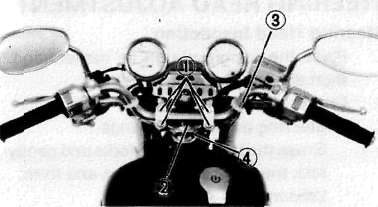
Steering Stem Nut:
110 Nm (11.0 m-kg, 80 ft*]
• Install the handlebar and torque the bolt 0 to specification.
Pinch Bolt: 20Nm(2.0m-kg, 14ft-lb)
Handlebar Bolt: 20 Nm (2.0 m-kg, 14 ft-lb)
WHEEL BEARINGS
Front Wheel Bearings
1. Raise the front end of the motorcycle, and spin the wheel by hand. Touch the axle or front fork while spinning the wheel-Excessive vibration — Replace bearings.
Rear Wheel Bearings
1. Remove:
• Rear wheel
2. Check:
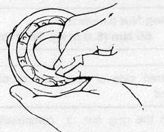
• Bearing movement Rotate with the fingers. Roughness/Wear — Replace.
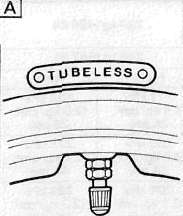
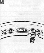
TUBELESS TIRES AND ALUMINUM WHEELS
• Always inspect aluminum wheels before a ride.
• Place the motorcycle on its centerstand and check for cracks, bends, or warpage of the wheels.
• Do not attempt any repairs to the wheel; replace any defective wheel.
• Do not attempt to use tubeless tires on a wheel designed for use with tube-type tire only. Tire failure and subsequent personal injury may result from sudden deflation.
• Be sure to install the proper tube when using tube-type tires.
• New tires have a relatively poor adhesion on the road surface so do not allow them to be subjected to high speed load from maximum speed until after a break-in run of approx. 100 km (60 mi).
• Always use the correct tire inflation pressure acording to the operating conditions.
|
Wheel |
Tire |
|
Tube type |
Tube type only |
|
Tubeless |
Tube type or tubeless |
|
A Tire |
C Tubeless tire |
|
B Wheel |
D Tube type tire |
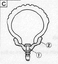
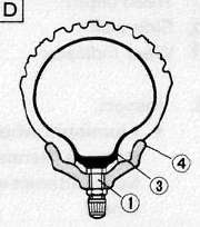
(1) Air valve
(2) Aluminum wheel (Tubeless type)
(3) Tube
(4) Aluminum wheel (tube type)
Always perform the following steps to ensure safe operation, maximum tire performance, and long service. 1. Measure:
• Tire pressure Out of specification — Adjust.
|
Basic weight: With oil and full fuel tank |
224 kg (494 lb) |
|
|
Maximum load * |
246 kg |
542 lb) |
|
Cold tire pressure |
Front |
Rear |
|
Upto90kg(198lb) load" |
177 kPa (1.8 kg/cm2. 26 psi) |
196 kPa (2.0 kg/cm2. 28 psi) |
|
90 kg (198 lb) load ~ 246 kg (542 lb) load- |
196 kPa (2.0 kg/cm*, 28 psi) |
275 kPa (2.8 kg/cm2. 40 psi) |
|
High speed riding |
206 kPa (2.1 kg/cm? 30 psi) |
225 kPa (2.3 kg/cm2 32 psi) |
* Load is the total weight of cargo, rider, passenger, and accessories.
2. Inspect:
• Tire surfaces Wear/Damage — Replace.
Minimum Tire Tread Depth: (Front and Rear) 1.0 mm (0.04 in)
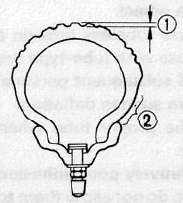
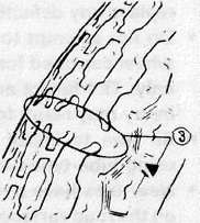
(1) Tread depth
(2) Side wall
(3) Wear indicator
3. Inspect:
• Aluminum wheels
Damage/Bends — Replace. Never attempt even small repairs to the wheel.
NOTE:
Always balance the wheel when a tire or wheel has been changed or replace.
Ride conservatively after installing a tire to allow it to seat itself properly on the rim.