Cleaning and Replacing the CMS Display/ Microcomputer
Cleaning and Replacing the CMS Display/ MicrocomputerCleaning and replacement
Use the following procedure to replace the LCD unit or the microcomputer unit.
1. Remove the headlight lens and the two headlight-body holding bolts. This will give you easy access to the instrument-panel holding nuts.
2. Disconnect the wire connectors in the headlight assembly that lead to the instrument panel.
3. Disconnect the speedometer cable.
4. Disconnect the instrument-panel holding nuts, and remove the panel.
5. Remove the three nuts which secure the instrument-panel mounting bracket, and remove the bracket.
6. Place the instrument panel assembly on a clean work surface, and remove the back panel.
7. Remove the four Phillips-head screws which secure the LCD/microcomputer, and remove the unit.
8. Remove the four screws which hold the LCD display holder.
9. Very carefully turn the display holder over, and completely remove the five display plate holding screws. Remove the LCD reflector and the display plate.
10. Detach the wire connector from its indexing points.
Disconnect the wire connector carefully. Do not pull on the wire connector. It is indexed and could be damaged if you pull on it. Do not touch the connector contacts. They are gold plated.
11. Remove the display plate and the LCD unit.
12. Clean the display plate and the LCD unit.
CAUTION:
a. Use compressed-air lens cleaner (as used on cameras) to clean the display and the LCD unit. Do not use shop air for this purpose.
b. Use a soft cloth. Do not use cotton. It will leave lint deposits which will interfere with the delicate contacts.
c. Very carefully clean the LCD unit because it is possible to generate enough static electricity to damage it.
13. Reinstall the LCD unit into the display holder.
Do not touch the LCD connector with bare hands.
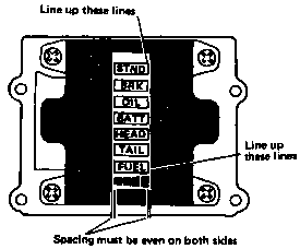
IMPORTANT NOTE:
The LCD unit must line up as shown in the illustration to seal the LCD unit properly.
14. Reinstall the LCD reflector so that the shiny surface faces toward the LCD unit.
15. Carefully place the wire connector on the LCD connector and seat it on its two indexing points. Install the display plate and carefully screw in the wire connector indexing screw first. Then screw in the remaining four holding screws. Do not overtighten the screws.
|
Tightening torque: |
|
|
3 mm: |
10cm-kg(0.7ft-lb) |
|
|
(Use LOCTITE) |
|
4 mm: |
24cm-kg(1.7ft-lb) |
16. Reinstall the display holder on the microcomputer.
IMPORTANT NOTE:
Before reinstalling the components, connect the LCD assembly to the motorcycle and check that it is function properly.
17. Reinstall the entire unit in the instrument panel.
18. Reinstall the instrument panel back to the motorcycle.
19. Check that the COM system is functioning properly.

