Chapter 1. General Information
Chapter 1. General InformationMOTORCYCLE IDENTIFICATION
Frame serial number
The frame seria number is stamped into the right side of the steering head pipe.
Starting serial number: XJ900RL 33F-001101
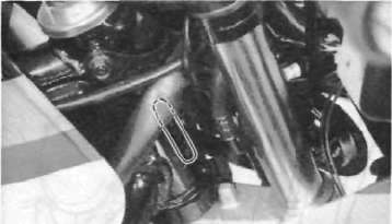
1. Frame serial number
Engine serial number
The engine serial number is stamped into the elevated part of the right rear section of the engine.
NOTE: The first three digits of these numbers are for model identifications; the remaining digits are the unit production number.
Starting serial number: 33F-001101
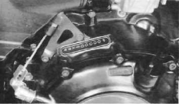
1. Engine serial number
SPECIAL TOOLS
The proper special tools are necessary for complete and accurate tune-up and assembly. Using the correct special tool will help to prevent damage from improper tools or improvised techniques.
For tune-up
1. Compression gauge P/N. 90890-03081
2. Inductive timing light P/N. 90890-03109
3. Inducive tachometer P/N. 90890-03113
4. Fuel level gauge P/N. 90890-01312
5. Vacuum gauge P/N. 90890-03094
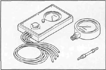
This gauge is needed for carburetor synchronization.
For engine service
1. Clutch holding tool P/N. 90890-04086
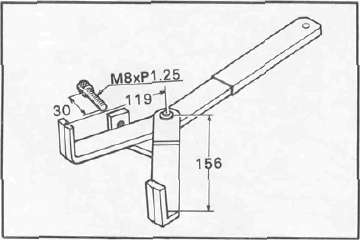
This tool is used to hold the clutch when removing or installing the clutch boss lock nut
2. Tappet adjusting tool P/N. 90890-01245
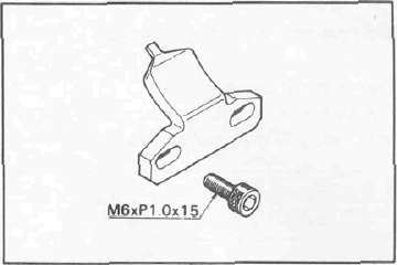
This tool is necessary to replace valve adjusting pads.
3. Valve guide reamer P/N. 90890-01227
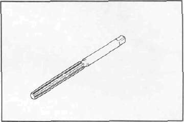
This must be used when replacing the valve guide.
4. Valve seat cutter set P/N. YM-91043
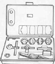
This tool is needed to re-surface the valve seat.
5. Valve guide remover P/N. 90890-01225
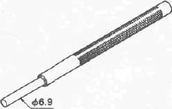
This must be used to remove the valve guides.
6. Valve guide installer P/N. 90890-04017
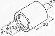
This tool is needed for proper installation of the valve guides.
7. Valve spring compressor P/N. 90890-04019
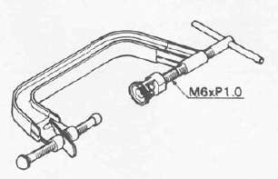
This tool must be used for removing and installing the valve assemblies.
8. Piston ring compressor P/N. 90890-04044
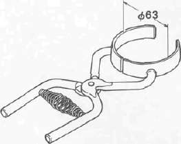
This is used to compress piston rings when installing the cylinder.
9. Piston base
P/N. 90890-01067
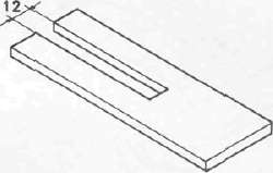
Use 4 of these to hold the piston during cylinder installation.
10. Rotor puller
P/N. 90890-01080

This tool is needed to remove the A. C. generator
11. Rotor puller attachment P/N. 90890-04052
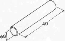
This tool is needed when removing the A. C. generator rotor together with the rotor puller.
12. Rotor holding tool P/N. 90890-04043
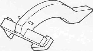
This tool is used to hold the A. C. generator rotor during removal and installation.
13. Piston pin puller P/N. 90890-01304
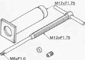
This tool is used to remove the piston pin.
14. Y. I. C. S. (Yamaha Induction control system) shut off tool P/N. 90890-04068
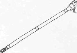
This tool is used to carburetor synchronization.
15. Plastigauge set "Green" P/N. YU-33210
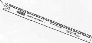
This gauge is needed when measuring clearance for connecting rod bearing.
For chassis service
1. T-handle
P/N. 90890-01326 Damper rod holder P/N. 90890-01365
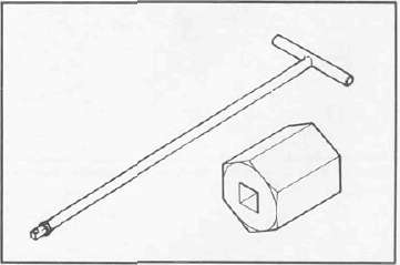
This tool is used to loosen and tighten the front fork cylinder holding bolt
2. Fork seal driver
P/N. 90890-01367
Fork seal driver attachment
P/N. 90890-01371
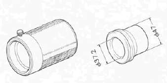
This tool used to reassemble the front fork.
For shaft drive service
1. Middle drive pinion holder P/N. 90890-04080
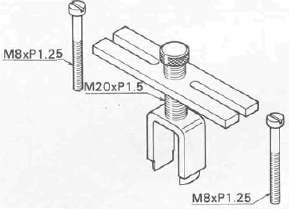
This tool is needed when measuring gear lash.
2. Middle and final gear holding tool P/N. 90890-01229
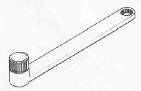
This tool is needed when measuring gear lasn.
3. Torx driver (# 40) P/N. 90890-04049
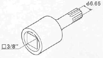
This tool is used to loosen or tighten the drive axle bearing stopper bolt
4. Dial gauge
P/N. 90890-03097
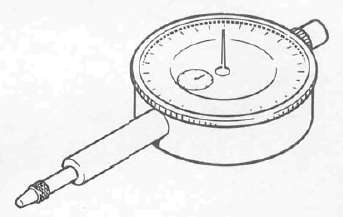
This too is used when measuring gear lash for middle and final gear.
5. Gear lash measurement tool (Final gear) P/N. 90890-01230
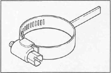
This tool is needed when measuring gear lash for final gear.