Chapter 8. Exploded Diagrams
Chapter 8. Exploded DiagramsEngine Components
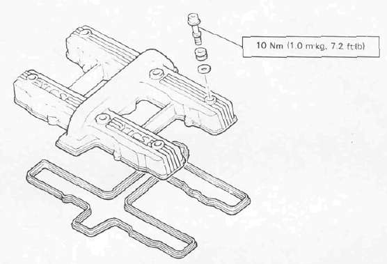
Engine ComponentsCYLINDER HEAD

VALVE

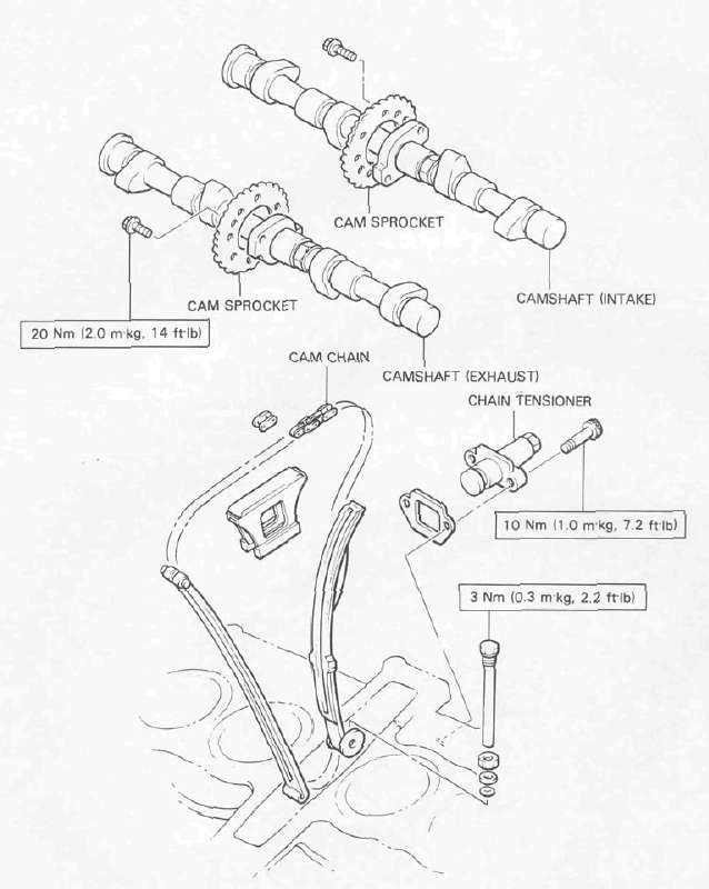
CAM CHAIN
CRANKSHAFT/PISTON

. WHEN INSTALLING THE CONNECTING ROD. BE SURE THAT THE SECURING NUTS ARE ON TOP.

OIL COOLER

Transmission Components
Transmission ComponentsCLUTCH

TRANSMISSION

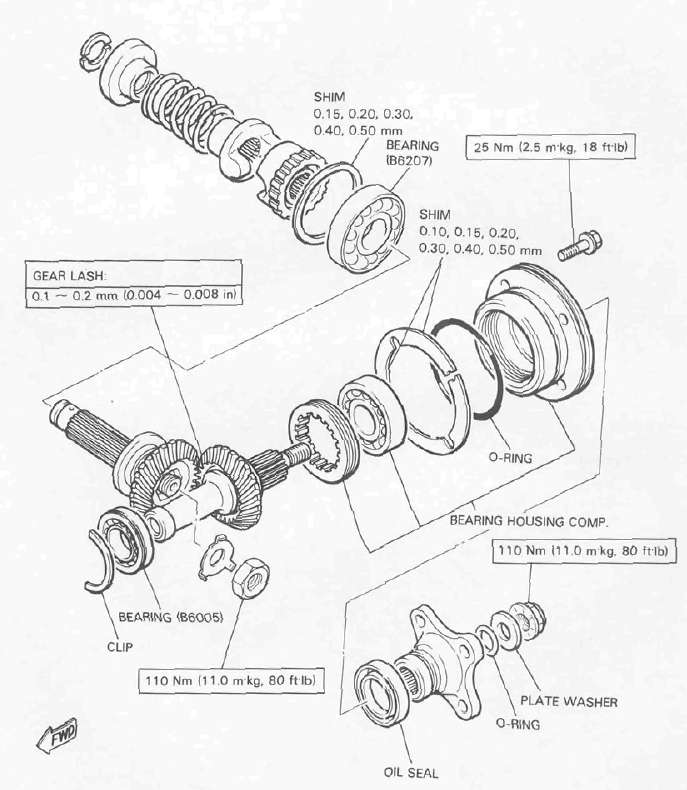
MIDDLE GEAR/DAMPER
Final Drive
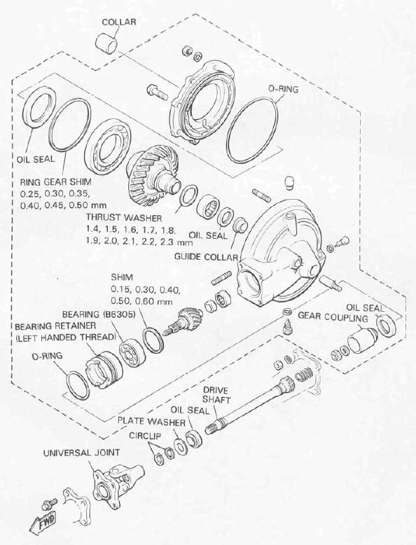
Final DriveFINAL GEAR/DRIVE SHAFT
Wheels and Brakes
Wheels and BrakesFRONT MASTER CYLINDER

| 1 | Master Cylinder |
| 2 | Brake hose |
| 3 | Brake pipe |
| 4 | Joint L/H |
| 5 | Joint R/H |
| 6 | Union bolt |
| 7 | Brake caliper |
| 9 | Motorcycle center |
REAR MASTER CYLINDER

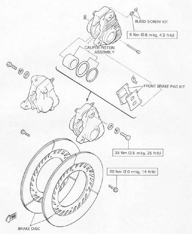
FRONT BRAKE CALIPER
REAR BRAKE CALIPER

FRONT WHEEL

REAR WHEEL

Suspension Components
Suspension ComponentsFRONT FORK

REAR SHOCK ABSORBER

SWING ARM

• APPLY LITHIUM-BASE GREASE
Lubrication Diagrams
Lubrication DiagramsLUBRICATION DIAGRAMS


Cable Routing
Cable RoutingCABLE ROUTING
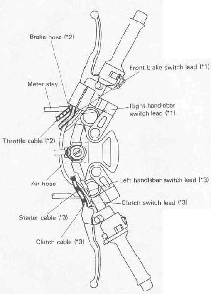
*1: Pass front brake switch lead and right handlebar switch lead behind air hose.
*2: Pass brake hose and throttle cable between air hose and meter stay.
*3: Pass clutch cable, clutch switch lead, left handlebar switch lead and starter cable behind air hose.
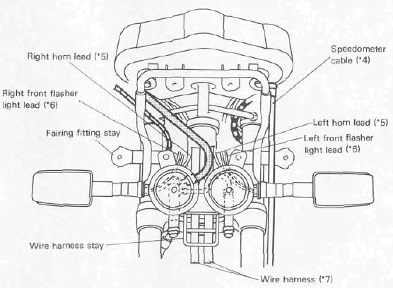
*4: Pass speedometer cable outside meter stay, in front of fairing fitting stay, and outside brake hose.
*5: Pass horn leads in front of brake joint.
*6: Pass front flasher light leads between horn and brake joint.
*7: Pass wire harness between under bracket and wire harness stay.

*1: Fasten ground lead together left ignition coil.
*2: Pass clutch cable between air cleaner joint #3 and #4

Electrical
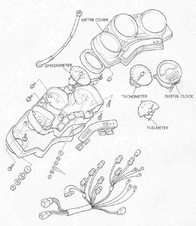
ElectricalSPEEDOMETER/TACHOMETER
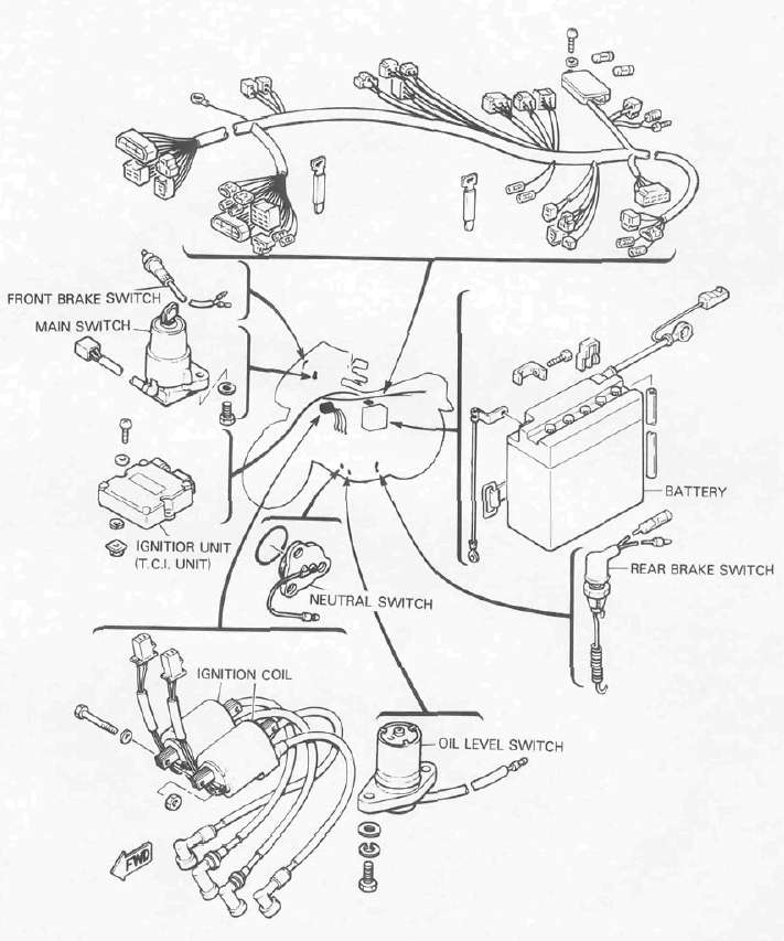
ELECTRICAL 1
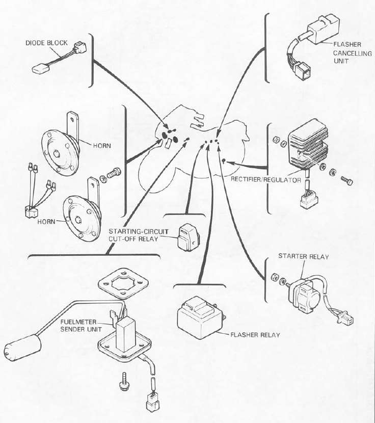
ELECTRICAL 2
WIRING DIAGRAM
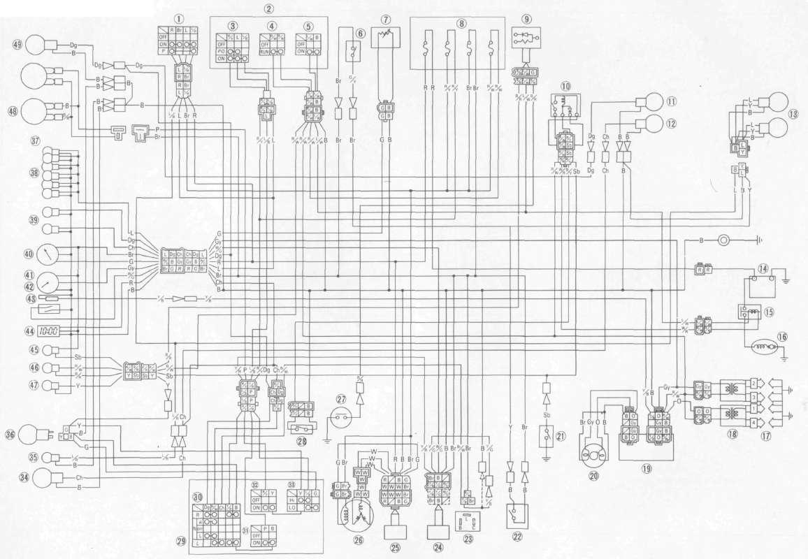
| 1. | Main switch |
| 2 | Handlebar switch (Right) |
| 3. | "LIGHTS" switch |
| 4. | "ENGINE STOP" switch |
| 5. | "START" switch |
| 6 | Front brake switch |
| 7. | Fuel sender |
| 8. | Fuse box |
| 9 | Diode |
| 10. | Starting-circuit cut-off relay |
| 11. | Rear flasher light (Right) |
| 12 | Rear flasher light (Left) |
| 13. | Tail/brake light |
| 14. | Battery |
| 15. | Starter relay |
| 16. | Starter motor |
| 17. | Spark plug |
| 18. | Ignition coil |
| 19. | Ignitor |
| 20. | Pick-up coil |
| 21 | Neutral switch |
| 22. | Rear brake switch |
| 23. | Flasher relay |
| 24. | Cancelling unit |
| 25. | Rectifier with regulator |
| 26. | AC. Generator |
| 27. | Oil level switch |
| 28. | Clutch switch |
| 29. | Handlebar switch (Left) |
| 30. | "TURN" switch |
| 31. | "HORN" switch |
| 32 | Passing light switch "PASS" |
| 33 | "LIGHTS" (Dimmer) switch |
| 34. | Front flasher light (Left) |
| 35 | Auxiliary light |
| 36. | Headlight |
| 37. | Meter assembly |
| 38. | Meter light |
| 39 | "TURN" indicator light |
| 40. | Fuelmeter |
| 41. | Tachometer |
| 42. | Over revolution switch |
| 43 | Reed switch |
| 44. | Digital clock |
| 45 | "NEUTRAL" indicator light |
| 46. | "OIL" indicator light |
| 47. | "HIGH BEAM" indicator light |
COLOR CODE
| 8r | Brown | Y | Yellow | L | Blue | R/W | Red/White | Y/B | Yellow/Black | Y/R | Yellow/Red | E | Ground |
| R | Red | Dg | Dark Green | P | Pink | L/W | Blue/White | Br/W | Brown/White | R/W | Red/White | B/R | Black/Red |
| W | White | Ch | Chocolate | 0 | Orange | L/B | Blue/Red | Y/G | Yellow/Green | L/R | Blue/Red | Gy | Gray |
| B | Black | Sb | Sky Blue | G | Green | R/Y | Red/Yellow | W/G | White/Green | G/Y | Green/Yellow | B/Y | Black/Yellow |
WIRING DIAGRAM
