900RL

Anti-Dive system

Submitted by xjcdadmin on Thu, 06/27/2013 - 10:26

System inspection

1.      Apply the front brake for a few minutes and check to see if any brake fluid leaks out of the pipe joints, the master cylinder, or the actuating piston housing.

2.      Check the fork for fork oil leakage.

3.      Turn the anti-dive adjusting bolt to the maximum position.

General Torque Specifications

Submitted by xjcdadmin on Thu, 06/27/2013 - 10:26

This chart specifies torque for standard fasteners with standard I.S.O. pitch threads. Torque specifications for special components or assemblies are included in the applicable sections of this book. To avoid warpage, tighten multi-fastener assemblies in a crisscross fashion, in progressive stages, until full torque is reached. Unless otherwise specified, torque specifications call for clean, dry threads. Components should be at room temperature.

Maintenance Intervals

Submitted by xjcdadmin on Thu, 06/27/2013 - 10:26

INTRODUCTION

This chapter includes all information necessary to perform recommend inspection and adjustments. These preventative maintenance procedures, if followed, will insure more reliable vehicle operation and a longer service life. The need for costly overhaul work will be greatly reduced. This information applies not only to vehicles already in service, but also to new vehicles that are being prepared for sale. Any service technician performing preparation work should be familiar with this entire chapter.

Sensors and Switches

Submitted by xjcdadmin on Thu, 06/27/2013 - 10:26

Fuel sender unit

1. Inspection

a.    Remove the sender unit from the fuel tank.

b.    Use a pocket tester (with ohm x 10 scale) for this check. Connect the pocket tester leads across the green lead and the black lead of the sender unit. The meter should show the following resistance at the specified fuel level. If not replace the sender unit.

Cable Routing

Submitted by xjcdadmin on Thu, 06/27/2013 - 10:26

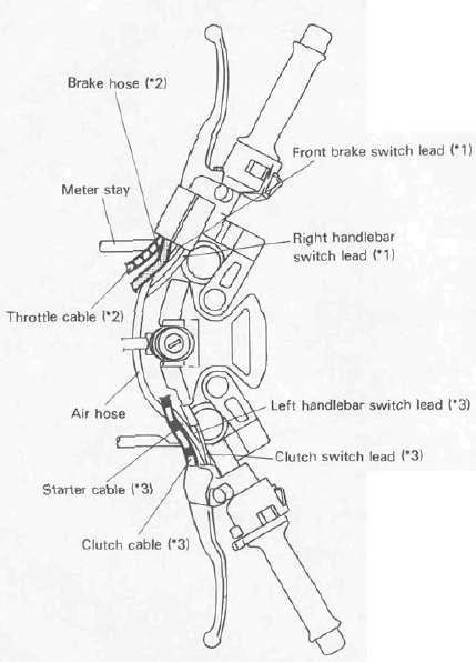
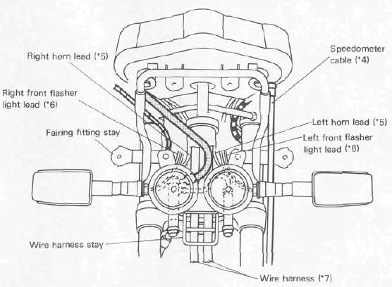
CABLE ROUTING

*1: Pass front brake switch lead and right handlebar switch lead behind air hose.
*2: Pass brake hose and throttle cable between air hose and meter stay.
*3: Pass clutch cable, clutch switch lead, left handlebar switch lead and starter cable behind air hose.

Front Wheel

Submitted by xjcdadmin on Thu, 06/27/2013 - 10:26

FRONT WHEEL

Removal

1.      Place the motorcycle on the center stand.

2.      Remove the speedometer cable from the speedometer.

3.      Remove the front fender securing bolts and remove the fender.