700NC (Maxim)

Oil Pump and Clutch -- Inspection and Repair

Submitted by xjcdadmin on Fri, 09/21/2018 - 08:13

J. Oil Pump

1. Check the clearance between housing and outer rotor.
Standard clearance B :
0.03 ~ 0.08 mm (0.0012 ~ 0.0031 in)

2. Check the clearance between outer rotor and inner rotor.
Standard clearance: 0.03 - 0.09 mm (0.001 - 0.003 in)

3 Check the rotor to housing clearance using a straight-edge.
Standard clearance: 0.03 - 0.08 mm (0.001 - 0.003 in)

Crankshaft, Con rods and Bearings -- Inspection and Repair

Submitted by xjcdadmin on Fri, 09/21/2018 - 01:04

I. Crankshaft

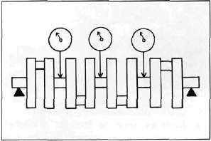
1. Crankshaft run-out

Support the crankshaft at both ends on V-blocks. Measure the amount of crankshaft run-out on the main bearing journals with a dial gauge while rotating crankshaft.

Run-out limit: 0.030 mm (0.0012 in)

If run-out exceeds limit, replace crankshaft.

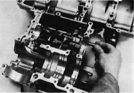
2. Inspection of bearings

Cylinder and Piston -- Inspection and Repair

Submitted by xjcdadmin on Fri, 09/21/2018 - 00:36

. Cylinder

1.    Inspect the cylinder walls for scratches. If vertical scratches are evident, the cylinder wall should be rebored or the cylinder should be replaced.

2.   Measure cylinder wall wear as shown. If wear is excessive, compression pressure will decrease. Rebore the cylinder wall and replace the piston and piston rings. Cylinder wear should be measured at three depths with a cylinder bore gauge. (See illustration.)

Cylinder Head and Valves -- Inspection & Repair

Submitted by xjcdadmin on Thu, 09/20/2018 - 22:30

INSPECTION AND REPAIR

A.   Cylinder Head Cover

Place head cover on a surface plate. There should be no warpage. Correct by re-surfacing as follows:

Place #400 or #600 grit wet sandpaper on surface plate and re-surface head cover using a figure-eight sanding pattern. Rotate head cover several times to avoid removing too much material from one side.

Lower Crankcase Disassembly

Submitted by xjcdadmin on Thu, 09/20/2018 - 22:26

L. Lower Crankcase

1.    Remove the dowel pin and "O-ring".

2.    Remove the shift fork guide bar and shift forks. The shift forks are identified by numbers cast on their sides.

3.    Remove the bolt securing the shift cam locating pin and remove the stopper plate and locating pin.

4.    Remove the neutral switch.

Cylinder Head Removal

Submitted by xjcdadmin on Thu, 09/20/2018 - 21:03

ENGINE OVERHAUL

A. Cylinder Head and Cylinder

1.    Remove the cylinder head cover.

2.    Remove the left crankcase cover (pickup coil cover).

3.    Remove the cam chain tensioner.