Middle Gear Adjustment
C. Middle Gear Servicing
1. Disassembly
Refer to page 39 for disassembly.
2. Inspection
Refer to page 52 for inspection.
3. Gear lash check
NOTE:
- Read more about Middle Gear Adjustment
- Log in to post comments
C. Middle Gear Servicing
1. Disassembly
Refer to page 39 for disassembly.
2. Inspection
Refer to page 52 for inspection.
3. Gear lash check
NOTE:
L. Transmission
1. Inspect each shift fork for signs of galling on gear contact surfaces. Check for bending. Make sure each fork slides freely on its guide bar.
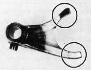
2. Roll the guide bar across a surface place. If the bar is bent, replace.
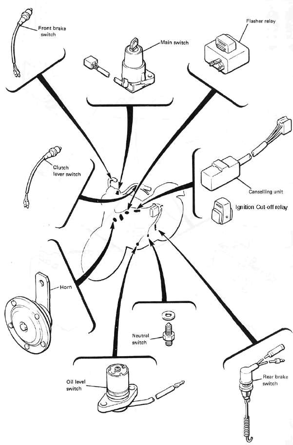
PARTS ILLUSTRATIONS
ELECTRICAL COMPONENTS

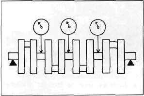
I. Crankshaft
1. Crankshaft run-out
Support the crankshaft at both ends on V-blocks. Measure the amount of crankshaft run-out on the main bearing journals with a dial gauge while rotating crankshaft.
Run-out limit: 0.040 mm (0.0016 in!
If run-out exceeds limit, replace crankshaft.
2. Inspection of bearings
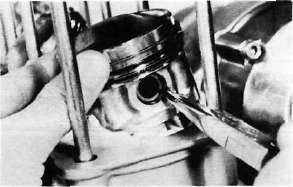
11. Pistons and Cylinder a. Install the pistons on the rods. The arrow on the piston must point to the front of the engine.
NOTE:
Before installing the piston pin clips, cover the crankcase with a clean rag so you will not accidentally drop the circlip into the crankcase. Always install new piston pin circlips.
INSPECTION AND REPAIR
A. Cylinder Head Cover
Place head cover on a surface plate. There should be no warpage. Correct by re-surfacing as follows:
Place #400 or #600 grit wet sandpaper on surface plate and re-surface head cover using a figure-eight sanding pattern. Rotate head cover several times to avoid removing too much material from one side.
SPECIFICATIONS
General Specifications
|
XJ750RH |
|
|
Basic color |
New Yamaha Black or Brilliant Red |
|
Dimensions: |
|
ELECTRICAL
A. Battery
1. The fluid level should be between the upper and lower level marks. Use only distilled water if refilling is necessary.
CAUTION:
Normal tap water contains minerals which are harmful to a battery; therefore, refill only with distilled water.
H. Oil Pump Removal and Disassembly
1. Remove the strainer cover. Note the wire harness clip position.
2. Remove the oil pump securing bolts and remove the sprocket cover and oil pump assembly.

CAUTION: