Lighting System
LIGHTING SYSTEM

Above circuit diagram shows only lighting circuit in wiring diagram.

B. Lighting Tests and Checks
- Read more about Lighting System
- Log in to post comments
LIGHTING SYSTEM
Above circuit diagram shows only lighting circuit in wiring diagram.
B. Lighting Tests and Checks
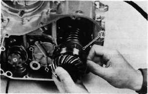
D. Valve Spring and Lifters
1. Checking the valve springs
a. This engine uses two springs of different sizes to prevent valve float or surging. The valve spring specifications show the basic value characteristics.
D. Remounting Engine
Refer to page 30 for engine removal. Reverse the applicable removal steps.
CAUTION:
Always use new bolts in the drive shaft coupling.
2. Install and tighten the engine mounting bolts.
|
Engine mounting bolt torque: |
F. Cylinder
1. Inspect the cylinder walls for scratches. If vertical scratches are evident, the cylinder wall should be rebored or the cylinder should be replaced.
2. Measure cylinder wall wear as shown. If wear is excessive, compression pressure will decrease. Rebore the cylinder wall and replace the piston and piston rings. Cylinder wear should be measured at three depths with a cylinder bore gauge. (See illustration.)
WIRING DIAGRAM
COLOR CODE
Proper periodic maintenance is important. Especially important are the maintenance services
related to emissions control. These controls not only function to ensure cleaner air but
are also vital to proper engine operation and maximum performance. In the following tables
of periodic maintenance, the services related to emissions control are grouped separately.
PERIODIC MAINTENANCE EMISSION CONTROL SYSTEM
J. Oil Pump
1. Check the clearance between housing and outer rotor.
|
Standard clearance: |
|
0.09 ~ 0.15 mm |
|
(0.0035 ~ 0.0059 in) |
6. Middle gear (installation only, refer to page 67 for the middle gear adjustment)
a. Install the middle drive gear assembly with the proper size of shim(s) and secure it with the bearing retainers and new "TORX" screws.
Tightening torque: 2.5 m-kg (18 ft-lb)
1. Shims
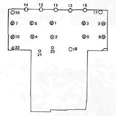
J. Crankcase Disassembly
1. Remove the upper crankcase bolts, starting the highest numbered bolt. Turn over the engine and remove the lower crankcase bolts,
CRANKCASE TORQUE SEQUENCE
UPPER CASE
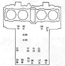
LOWERCASE
G. SIGNAL SYSTEM
Above circuit diagram shows only signal circuit in wiring diagram.

B. Signal System Tests and Checks
