OIL PUMP AND OIL PAN

1 Chain cover
2 Oil pump sprocket
3 Oil pump drive sprocket
4 Oil pump cover
5 Inner rotor
6 Spring
7 Relief valve
8 Shaft
9 Dowel pin
10 Outer rotor
11 Dowel pin
12 O-ring

1. Install:
• O-ring 1 onto the oil pump assembly
• Chain
• Oil pump assembly
• Chain cover
Oil Pump: 12 Nm (1.2 m-kg, 8.7 ft-lb)
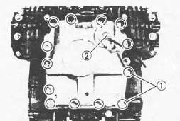
2. Install:
• Oil pan
• Wire clamps 1
• Bolts
• Oil level switch 2
Oil Pan: 12 Nm (1.2 mkg, .7 ft-lb)
Oil Level Switch: 8 Nm (0.8m-kg, 5.8 ft-lb)
CLUTCH

1 Plate washer
2 Oil seal
3 Bearing
4 Pinion gear
5 Plate washer
6 Circlip
7 Lock washer
8 Friction plate
9 Clutch plate
10 Wire clip
11 Clutch plate
12 Clutch boss spring
13 Spring seat
14 Thrust plate
15 Spacer
16 Bearing (15-28)
17 Oil pump drive sprocket
18 Collar
19 Thrust plate
20 Pull rod
21 Bearing
22 Water pump drive shaft
23 Spacer
24 Water pump drive gear
Note:
The outermost friction plate has a V-cut in it. Give some identifying mark to the corresponding dog in the clutch housing.
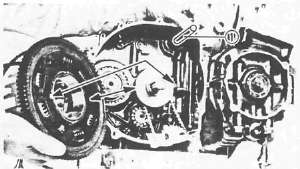
CLUTCH AND OIL PUMP DRIVE SPROCKET
1. Install:
• Thrust plate 1
• Oil pump drive sprocket 2
12 Nm (1.2m-kg, 8.7 ft-lb)
2. Hook the drive chain on the drive sprocket.
3 Install:
• Collar 3
4. Install:
• Water pump drive shaft 1
• Clutch housing
CAUTION:
Be sure that the oil pump drive gear tabs engage the clutch housing grooves on its back or the tabs will be damaged when tightening the clutch boss securing nut.

5. Install:
• Bearing 1
• Spacer 2
• Thrust plate 3
• Clutch boss 4
• Lock washer (New) 5
• Nut 6
Clutch Boss: 70 Nm (7.0 m kg, 50 ft lb)
6. Bend lock washer tabs against the nut flats.
7. Install:
• Friction plates
• Clutch plates

8. Install:
• Friction plate (with V-cut 1 in tab)
NOTE:
Install the friction plate so that the V-cut tab is in the identified dog 2 . If you forget to identify the position with a mark, measure the width of each dog. 13.8 mm (0.543 in) width is for that position. The other width are 14 mm (0.551 in).

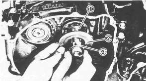
9. Install:
• Plate washer 2
• Thrust bearing 3 onto the pull rod 4
• Pull rod 4 into the pressure plate 1
10. Install:
• Pressure plate
NOTE:
Align a dot on the clutch boss with a dot on the pressure plate.
• Clutch springs
Clutch Spring: 8 Nm (0.8 m-kg, 5.8 ft-lb)
11. Install:
• Oil baffle plate
• Dowel pins
• Gasket
• Clutch cover

NOTE:
Set the gear of the clutch pull rod facing approximately 45° from horizontal toward the rear.

• Set the clutch lever 1 on the right crankcase cover parallel to the gasket surface.
• Make sure that the punch mark on the lever 2 align with the mark on the crankcase cover 3 when pushing the lever towards the front by hand.
Clutch Cover: 1 2 Nm(1.2m-kg,8.7ft-lb)

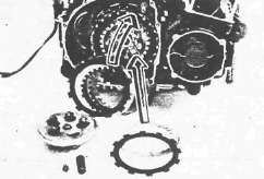
12. Install:
• Spacer 1
• Water pump drive gear 2
• Water pump drive gear cover.
Water Pump Drive Gear: 12 Nm (1.2 m-kg, 8.7 ft-lb) LOCTITE®
Cover: 8Nm(0.8m-kg, 5.8ft-lb)
- Printer-friendly version
- Log in to post comments