CAUTION:
Disc brake components rarely require disassembly. Do not disassemble components unless absolutely necessary. If any hydraulic connection in the system is opened, the entire system should be disassembled, drained, cleaned and then properly filled and bled upon reassembly. Do not use solvents on brake internal components. Solvents will cause seals to swell and distort. Use only clean brake fluid for cleaning. Use care with brake fluid. Brake fluid is injurious to eyes and will damage painted surfaces and plastic parts.
A. Caliper pad replacement
It is not necessary to disassemble the brake caliper and brake hose to replace the brake pads.
1. Remove the front fender and front wheel.
2. Unhook the pad retaining pin clip and remove the clip.
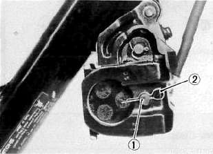
1. Pad retaining pin 2. Clip
3. Pull out the pad retaining pin.

1. Pad retaining pin
4. Remove the pads.
5. Install the new brake pads and shims. Before installing the pads, install the shim on the back plate which faces the caliper piston, as shown. Also replace the following parts if pad replacement is required.
a. Pad spring
b. Shim
c. Pad retaining pin
d. Clip
NOTE:
Replace the pads as a set if either is found to be worn to the wear limit.

1. Shim 2. Disc rotating direction

B. Caliper disassembly

1. Remove the brake hose from the caliper. Allow the caliper assembly to drain into a container.
2. Place the open hose end into the container and pump the old fluid out of the master cylinder.
3. Remove the pad spring, shim, pad retaining pin, clip and pads.
4. Remove the brake caliper holding bolt from the front fork.
5. Remove the dust seal.
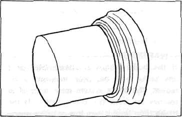
6. Carefully force the piston out of the caliper cylinder with compressed air. Never try to pry out the piston.
WARNING:
Cover the piston with a rag. Use care so that piston does not cause injury as it is expelled from the cylinder.
7. Remove the piston seal.
C. Master cylinder disassembly
1. Remove the brake light switch.
2. Remove the brake hose.

3. Remove the brake lever and spring.
4. Remove the master cylinder from the handlebar. Remove the cap and drain the remaining fluid.
5. Remove the master cylinder dust boot.
6. Remove the snap ring.

7. Remove the master cylinder cup assembly. Note that the cylinder cups are installed with the larger diameter (lips) inserted first.
D. Brake inspection and repair
Recommended Brake Component Replacement Schedule:
Brake pads; As required
Piston seal, dust seal; Every two years
Brake hoses; Every four years
Brake fluid; Replace only when brakes are disassembled
1. Replace the caliper piston if it is scratched.
2. Replace any brake pad worn beyond limits. Always replace the brake pads as a set.
See Caliper Pad Replacement procedure for a listing of the parts to be replaced when pads are replaced.
Wear limit: 4.0 mm (0.16 in)
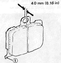
1. Wear indicator
3. Replace piston and dust seals if damaged. Replace seals every two years.
4. Inspect master cylinder body. Replace if scratched. Clean all passages with new brake fluid.
5. Inspect the brake hoses. Replace every four years or immediately if cracked, frayed, or damaged.
6. Check for wear and deflection of disc.

Maximum deflection: 0.15 mm (0.006 in)
Minimum disc thickness: 4.5 mm (0.18 in)
If disc is worn beyond minimum thickness or deflection exceeds specified amount, replace disc.
E. Brake reassembly
1. Caliper reassembly
All internal parts should be cleaned in new brake fluid only. Internal parts should be lubricated with brake fluid when installed. Replace the following parts whenever a caliper is disassembled.
Bleed screw and rubber cap
Piston seal
Dust seal

a. Install the piston seal and piston.
b. Install the pads.
2. Install the caliper assembly on the front fork.

Caliper holding bolt torque: 4.5 m-kg (32.5 ft-lb)
4. Attach the brake hoses.
Brake hose torque: 2.6 m-kg (19.0 ft-lb)
5. Brake disc assembly
If brake disc has been removed from hub or is loose, tighten bolts. Use new locking washers and bend over locking
tabs after bolts are tightened.
Disc bolt torque: 2.0 m-kg (14.5 ft-lb)
6. Master cylinder reasembly
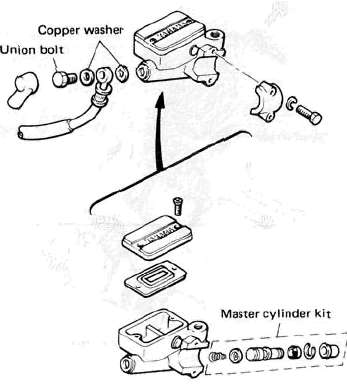
Reassemble master cylinder as shown in illustration.
Brake hose torque: (all brake union bolts) 2.6 m-kg (19.0 ft-lb)
7. Air bleeding
WARNING:
If the brake system is disassembled or if any brake hose has been loosened or removed, the brake system must be bled to remove air from the brake fluid. If the brake fluid level is very low or brake operation is incorrect, bleed the brake system. Failure to bleed the brake system properly can result in a dangerous loss of braking performance.
a. Add proper brake fluid to the reservoir. Install the diaphragm, being careful not to spill or overflow the reservoir.
b. Connect the clear plastic tube of 4.5 mm (3/16 in) inside diameter tightly to the caliper bleed screw. Put the other end of the tube into a container.

c. Slowly apply the brake lever several times. Pull in the lever. Hold the lever in "on" position. Loosen the bleed screw. Allow the lever to travel slowly toward its limit. When the limit is reached, tighten bleed screw. Then release the lever.
d. Repeat step "c" procedure until all air bubbles are removed from system.
NOTE:
If bleeding is difficult, it may be necessary to let the brake fluid system stabilize for a few hours. Repeat the bleeding procedure when the tiny bubbles in the system settle out.
- Printer-friendly version
- Log in to post comments