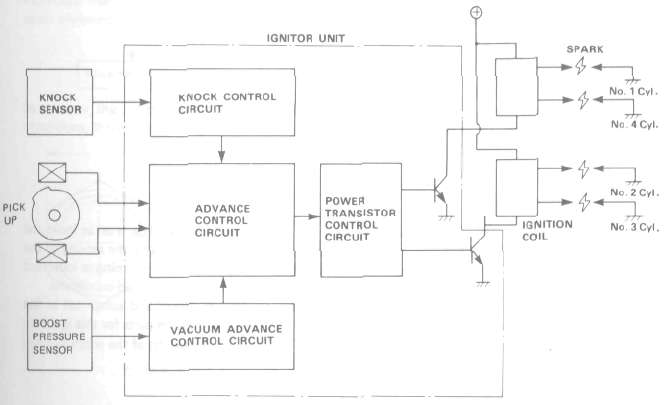
This motorcycle is equipped with the conventional transistor advance system as well as a semi conductor controlled boost sensor and a knock sensor. These combine to produce the optimum ignition timing according to engine conditions (i.e., engine speed, load, knocking, etc.).
Ignition system block diagram
VACUUM ADVANCE CONTROL SYSTEM
Generally speaking, in a 4-stroke motorcycle, the knocking zone varies with engine load.

In an advance system concerned only with engine speed, the ignition advance is set as indicated by the heavy broken line (-------------}, whereas in the advance system assisted by the sensing of the engine load conditions, the optimum ignition can be obtained by setting the timing as indicated by the lighter broken line (-------------). This is the case especially under partial-load conditions.
Engine load conditions are monitored by a semiconductor boost sensor and computed in the electronic circuit for the control of ignition timing. The absence of moving parts for this ignition-timing system contributes to the longer life, smaller size, and lighter weight of the entire system.
KNOCK SENSOR
The knock sensor senses the high-frequency vibrations developed by the engine and, as soon as this takes place, this knock sensing system retards the ignition timing gradually so that knocking can be suppressed.
When there is no knocking for a certain period of time, this system functions to advance the ignition timing very gradually, until knocking is about to occur. This sensor feeds back the vibrations from the knocking engine and thereby controls the ignition timing so it is always set at an advanced position, but just before knocking would occur.

In this way, this knock-control system makes it possible to deal with constantly varying operating conditions, thereby supplying the constant and optimum ignition timing and spark.


This sensor which is mounted between #2 and #3 cylinders on the exhaust side, employs a combined piezoelectric element and terminal place. This unit senses high-frequency oscillations caused by engine knocking. The oscillations are a form of pressure, and this pressure generates electrical voltage in the piezo element. The generated voltage is carried to the ignitor unit, and this signal retards the timing, preventing the engine from knocking.
Fail-safe functions
If the knock sensor fails because of a lead failure, short-circuit, couple disconnection, or sensor
damage, the ignitor unit automatically retards ignition timing from the advanced setting.
(1} If the pressure sensor is disconnected, the ignition unit automatically retards the ignition
timing to the curve (1) shown in the illustration. (2) If the knock sensor output is zero, the ignitor unit automatically retards 5 ± 1.5° from the
advanced setting, the safest setting over 7,500 rpm.

PRESSURE SENSOR
This boost sensor unit consists of a semiconductor strain gauge and an amplifying circuit. Pressure to the carb manifold {venturi portion) is sensed by the strain gauge and amplified in the circuit connected with this gauge. The amplified pressure signals are than transmitted to the ignition system for the control of ignition timing advance.


PRESSURE SENSOR INSPECTION (OFF-FRAME)
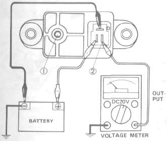
Open the pressure intake tube 1 to the atmosphere, and check the voltage between the output terminal 2 and the ground. See the following picture.
Output voltage: About 2.0 DC. volt

1. Remove the seat.
2. Remove the side panels as one piece.
3. Remove the stay 1.
4. Pull out the TCI unit connecter and connect a Yamaha Pocket Tester.

+ lead-Black/Red - lead -Black/Yellow
5. Turn the main switch key to ON; or connect the battery
+ lead to R/W and - lead to ground.
6. Read the tester. If the tester reading is not in the vicinity of the specified range, replace the pressure switch.
Specified range: About 2.0 DC. volt
- Printer-friendly version
- Log in to post comments