ANTI-DIVE SYSTEM
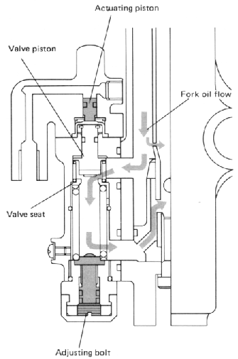
Normal oil flow -- no brakes applied.
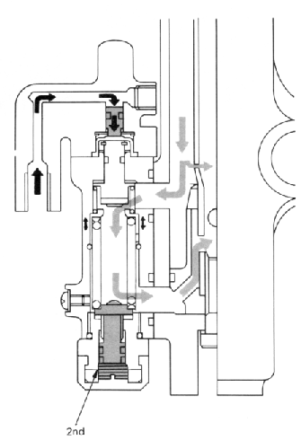
Oil flow as brakes are applied. Brake fluid pressure begins to move actuating piston against the small spring, pushing piston against seat, thereby restricting oil flow from the outside of the fork tube to the inside.
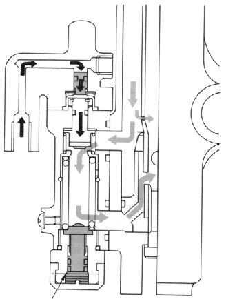
Adjuster fully extended -- all lines showing.
Oil flow as the adjusting bolt is set to the minimum effect. As the fork tries to compress, pressure builds on the seat, overcoming the pressure of the large spring, allowing the seat to move and fluid to pass from outside to inside the tube.
NOTE: Some fluid is always allowed to pass through the restricted passage above the anti-dive ports.
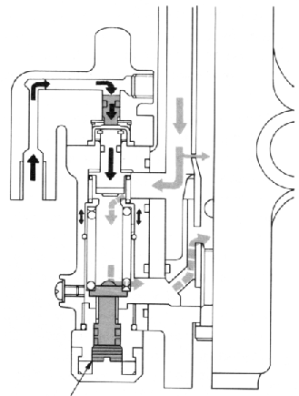
Adjuster fully seated -- head flush with notch.
Oil flow as the adjusting bolt is set to the maximum effect. The bolt applies greater force to the large spring, increasing the pressure required to move the seat.
System inspection
1. Apply the front brake for a few minutes and check to see if any brake fluid leaks out of the pipe joint and/or the vent.
2. Check the fork for fork oil leakage.
3. Turn the anti-dive adjusting bolt to the maximum position.
4. Compress the front forks while applying the front brake. If the front forks are compressed easily, the anti-dive system may be damaged.
Removal
1. Release the air from the front fork by pressing the air valve pin.
2. Remove the drain screw from the anti-dive valve housing and drain the fork oil.
3. Remove the brake hose from the actuating piston housing.
4. Remove the bolts securing the actuating piston housing, and remove the housing from the anti-dive valve housing.
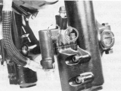
Remove the anti-dive adjusting bolt cover and remove the adjusting bolt seat.
The adjusting bolt can not be removed from its seat.
6. Remove four bolts securing the anti-dive valve assembly and remove the housing assembly from the front fork. Remove two O-rings from the front fork.
Inspection
NOTE:
The anti-dive valve housing can not be disassembled so it must be replaced with a new one if the anti-dive valve malfunction is found.
1. Remove the circlip and remove the actuating piston from the actuating piston housing.
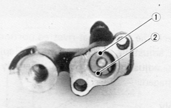
1. Circlip 2. Actuating piston
Do not remove the O-ring from the actuating piston.
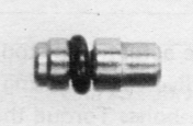
2. Check the piston, O-ring, and cylinder for wear, cracks, rust, and/or scrathces. If any damage is found, replace the actuating piston housing assembly.
3. Check the piston separator for cracks and replace if damaged.

4. Check the spring seat rivetted portion of the adjusting bolt for damage. Replace the adjusting bolt seat assembly if damaged.
Assembly
1. Lubricate the actuating piston with clean brake fluid, and carefully insert the piston into the actuating piston housing cylinder until the shoulder of the piston is flush with the cylinder edge.
2. Install the washer and circlip.
3. Install the separator into the actuating piston housing.
4. Install new O-rings around the front fork oil passages.
5. Install the anti-dive valve housing onto the front fork and secure it with four bolts. Torque the bolts to the specification.
Tightening torque: 0.8 m-kg (5.8 ft-lb)
6. Install the actuating piston housing onto the anti-dive valve housing and secure it with two bolts. Torque the bolts to the specification.
Tightening torque: 0.4 m-kg (2.9 ft-lb)
7. Install a new O-ring onto the adjusting bolt seat and apply a thread locking compound. Install the adjusting bolt seat assembly and tighten it to the specification.
Tightening torque: 2.0 m-kg (14.5 ft-lb)
8. Connect the brake hose to the actuating piston housing with the union bolt and copper washers. Torque it to the specification.
Tightening torque: 2.6 m-kg (18.8 ft-lb)
9. Pour the specified amount of front fork oil into the fork inner tube.
Front fork oil capacity (each leg):
309 cc (10.5 oz) Recommended oil:
Yamaha fork oil 20Wt or equivalent
10. Add proper brake fluid into the brake reservoir being careful not to spill or overflow.
11. Connect the clear plastic tube of 4.5 mm in inside diameter tightly to the actuating piston housing bleed screw. Put the other end of the tube into a container.
12. Slowly apply the brake lever several times. Pull in the lever. Hold the lever in the "on" position. Loosen the bleed screw. Allow the lever to travel slowly toward its limit. When the limit is reached, tighten the bleed screw. Then release the lever.
13. Repeat the above step until all air bubbles are removed from the brake line. It may be necessary to bleed the caliper cylinder in the same manner.
NOTE:
If the bleeding is difficult, it may be necessary to let the brake fluid in the system stabilize for a few hours and repeat the bleeding procedure.
14. Fill the fork with air using a manual air pump or other pressurized air supply.
Standard air pressure: 0.4 kg/cm2 (5.7 psi)
15. Adjust the anti-dive adjusting bolt.
- Printer-friendly version
- Log in to post comments