
Removal and disassembly
WARNING: Securely support the motorcycle so it won't fall over when the front wheel and front forks are removed.
1. Remove the front wheel. Refer to "FRONT WHEEL"
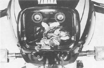
2. Remove the windscreen assembley.
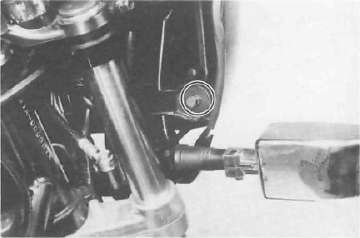
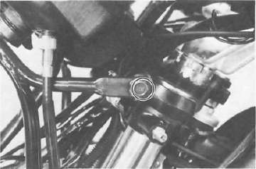
3. Remove the actuating piston housing securing bolts, and remove the actuating piston housing from the anti-dive valve assembly.

4. Remove the caliper cylinder securing bolts.
NOTE: Do not depress the brake lever when the wheel is off the motorcycle as the brake pads will be forced shut.

5. Remove the fork air valve cap and depress the valve until the air pressure escapes completely from the both forks.
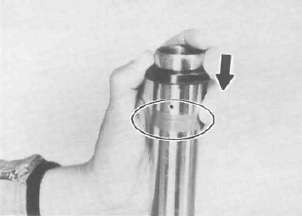
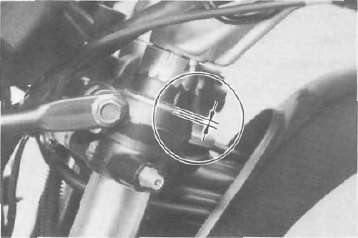
6. Remove the rubber cap from the top of the fork.
NOTE: Before loosen the fork pinch bolts, loosen the fork cap bolt.
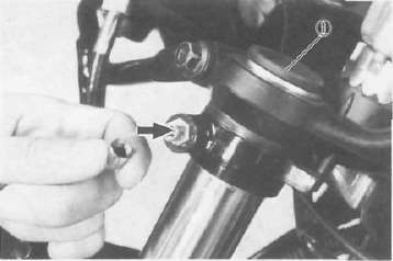
1. Rubber cap
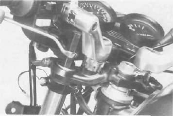
7. Loosen the fork pinch bolts in the handle crown and under bracket.
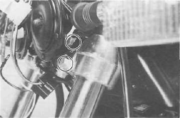
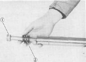
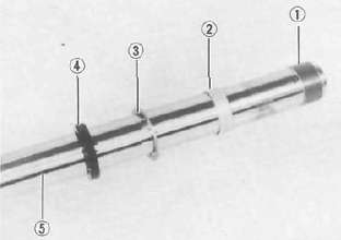
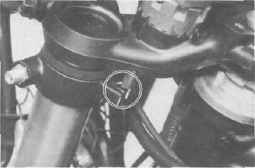
8. Remove the damper, air joint pipe bracket and circlip.

1. Damper 2. Air joint pipe 3. Circlip
9. Slide the inner fork tube out of the handle crown and under bracket Remove the front forks.

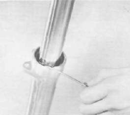
10. Remove the dust seal with a thin screwdriver. Take care not to scratch the inner fork tube. Discard the dust seal.

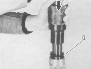
11. Remove the cap bolt and fork spring.
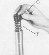
1. Cap bolt 2. Fork spring
12. Place an open container under the fork and turn the fork upside down and drain the oil.
NOTE: Do not remove the drain bolt from outer fork tube, the cylinder securing bolt can not be removed unless the drain bolt is in place.
13. Remove the anti-dive valve assembly from the bottom of the fork.

14. Remove the cylinder securing bolt from the bottom of the outer fork tube.
15. Remove the damper rod (cylinder complete) and rebound spring.
1. Damper rod (Cylinder complete) 2. Rebound spring
16. Remove the retaining clip and back-up ring from the outer fork tube.
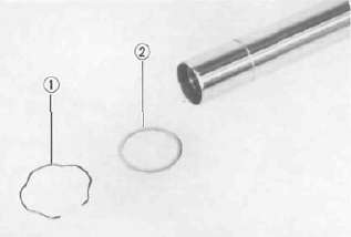
1. Retaining clip 2. Back-up ring
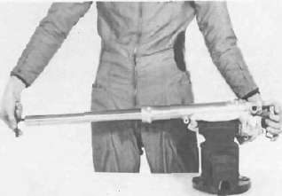
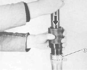
17. Hold the front fork outer tube in a vise horizontally. Put in the inner fork tube just before it bottoms out and then pull it back quickly.Repeat this step until the inner fork tube can be pulled out from the outer fork tube (usual 2 or 3 times). Then, the oil seal, seal spacer, guide bush, and slide bush all come out together, and remove the two valve springs, oil lock piece valve, and oil lock piece.
CAUTION: Don't bottom out the inner fork tube in the above step, or the oil lock piece valve and oil lock piece will be damaged.
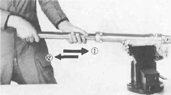
1. Put in slowly 2. Pull back quickly
1. Slide bush 2. Guide bush 3. Seal spacer 4. Oil seal 5. Inner fork tube
Inspection
Clean and inspect all front fork components. Replace any worn or damaged components prior to reassembly.
1. Check the inner fork tube and replace if the tube is badly scratched or bent.
WARNING: Do not attempt to straighten a bent inner fork tube as this may dangerously weaken the tube.
2. Check the outer surface of the fork seal seat and outer surface of the back-up ring seat in the outer fork tube for damage. Replace the tube if for necessary.
3. Check the outer tube for dents. Replace the tube if for necessary.
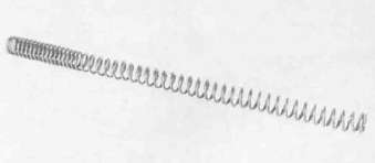
4. Check the free length of the fork spring.
Fork spring free length: 522.5 mm (20.6 in)
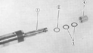
5. Check the 0-ring of the cap bolt air joint pipe bolt, and air joint cover. Replace any damaged 0-ring.
6. Check the damper rod for wear, damage, or contamination. Blow out all oil passages with compressed air. If it is worn or damaged, replace it.

7. Check the oil lock piece valve and oil
lock piece. Replace it, if damaged.
Reassembly
NOTE: In front fork reassembly, be sure to use following new parts.
Valve spring
Guide bush
Slide bush
Oil seal
Dust seal
1. Make sure all components are clean before reassembly.
2. Install the rebound spring to the damper rod.
3. Slide the damper rod into the inner fork tube from its top.
4. Fit the two valve springs, oil lock piece valve and oil lock piece in that order over the damper rod sticking out of the inner fork tube.
1. Damper rod 2. Oil lock piece valve 3. Valve spring
4. Oil lock piece
5. Insert the inner fork tube in the outer fork tube.
NOTE: For this insertion, mate the threaded end hole of the damper rod and the hole in the outer fork tube bottom end, and also mate the lower oil passage of the four in the oil lock piece and the lowest hole in the side of the outer fork tub.
6. Apply thread-locking compound such as LOCTITE to the cylinder securing bolt and install it. Torque the bolt to specification.
Tightening torque:
23 Nm (2.3 mkg, 17 ft-lb)
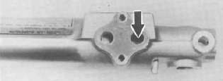
7. Install the anti-dive valve housing onto the front fork and secure it with bolts. Torque the bolts to specification.
NOTE: Before installing the anti-dive valve housing, install the O-rings around the front fork oil pasages.
Tightening torque:
7 Nm (0.7 mkg, 5.1 ft-lb)
8. Install the guide bush by pressing it in with special tool. Then, install the seal spacer into the outer fork tube.
1. Guide bush
9. Apply oil to the oil seal, and install the oil seal by pressing it in with special tool. Then, install the back-up ring and retaining clip.
NOTE: Before appling oil, tape the inner tube over its groove so that the groove edge will not damage the oil seal lip.
1. Oil seal
10. Install the dust seal and fork spring.
NOTE: When installing the fork springs, the greater pitch should be at the bottom. The main fork spring has a small coil diameter at the bottom.
11. Pour the specified amount of recommended fork oil into the inner fork tube.
Fork oil capacity (each fork): 286 ± 4 cm3 (10.1 ± 0.14 Imp oz, 9.67 ± 0.14 US oz) Recommended oil:
SAE 5W type SE motor oil or equivalent
12. After filling, slowly pump the forks up and down to distribute the oil and temporarily install the cap bolt.
13. Slide the fork into the under bracket.
14. Apply a light coat of lithium soap base grease to the O-rings in the air joint bracket. Install the circlip, air joint bracket and damper over the inner fork tube.
15. Slide the fork into the handle crown in the following way.
a. Make sure the projecting portion (stopper) of the air joint bracket is positioned correctly.
b. Fit the front fork by pushing it up until its top is flush with the handle crown top end. Holding the front in this position, temporarily tighten the pinch bolts with fingers.
16. Tighten the fork pinch bolts at the handle crown and under bracket. Then, tighten the cap bolt.
Tightening torque: Handle crown: 20 Nm (2.0 mkg, 14 ff-lb) Under bracket: 23 Nm (2.3 mkg, 17 ft-lb) Cap bolt: 23 Nm (2.3 mkg, 17 ft-lb)
1 7. Fit the fork with air using a manual air pump or other pressurized air supply.
Standard air pressure: 39.2 kPa (0.4 kg/cm2, 5.7 psi)
18. Install the air valve cap.
19. Install the caliper cylinder, the actuating piston housing and the front wheel. Refer to "FRONT WHEEL".
Tightening torque: Caliper cylinder: 35 Nm (3.5 mkg, 25 ft lb) Actuating piston housing: 5 Nm (0.5 mkg, 3.6 ft-lb)
- Printer-friendly version
- Log in to post comments