Clutch assembly
a. Install the primary drive gear and collar.
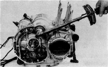
Tightening torque: 5.0 m-kg (36.0 ft-lb)
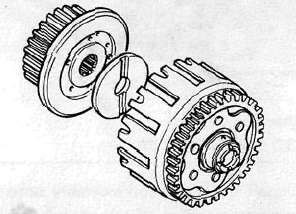
b- Install the primary driven gear assembly.
c. Install the clutch boss and thrust plate.
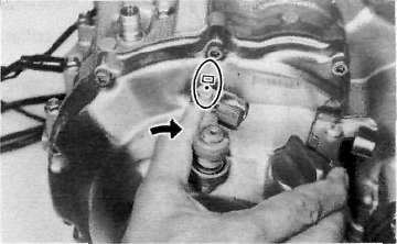
d. Install a new lock washer and nut and tighten the nut to the specified torque. Use the clutch boss holder (special tool).
Tightening torque: 7.0 m-kg (50.5 ft-lb)
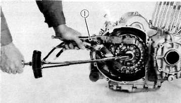
1. Clutch boss holder
e. Bend the lock washer tabs along the nut flats.
f. Install the clutch plates and friction plates alternately on the clutch boss, starting with a friction plate and ending with a friction plate.
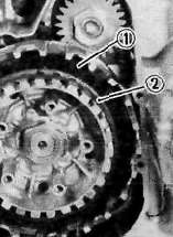
1. Third friction plate 2. Clutch boss spring
g. Install the plate washer, thrust bearing, and clutch pull rod into the clutch pressure plate from inside.
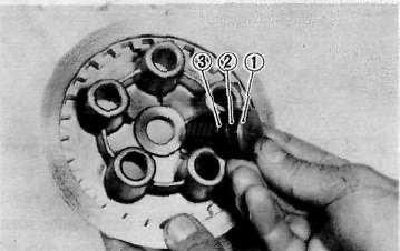
1. Pull rod 2. Thrust bearing 3. Plate washer
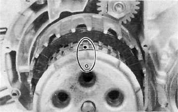
h. Install the pressure plate assembly onto the clutch boss.
NOTE:
Pressure plate has a dot on it which must line up with the dot on clutch boss.
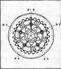
i. Install the clutch springs and screws. Tighten the screws.
Clutch screw torque: 0.8m-kg(5.8ft-lb)
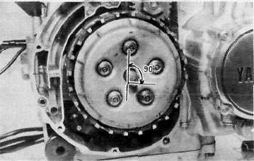
j. Set the gear of the clutch pull rod on the pressure plate facing approximately 90° from horizontal toward the rear; set the clutch lever (if installed) on the right crankcase cover parallel to the gasket surface and install the cover to the crankcase. Do not forget to install two dowel pins.
k. If the clutch lever has been removed, install the lever return spring and lever on the shaft after installing the right crankcase cover. In this case make sure that the punch mark on the lever should align with the mark on the crankcase cover when pushing the lever towards the front by hand and then install the circlip.
- Printer-friendly version
- Log in to post comments