Upper Crankcase Assembly
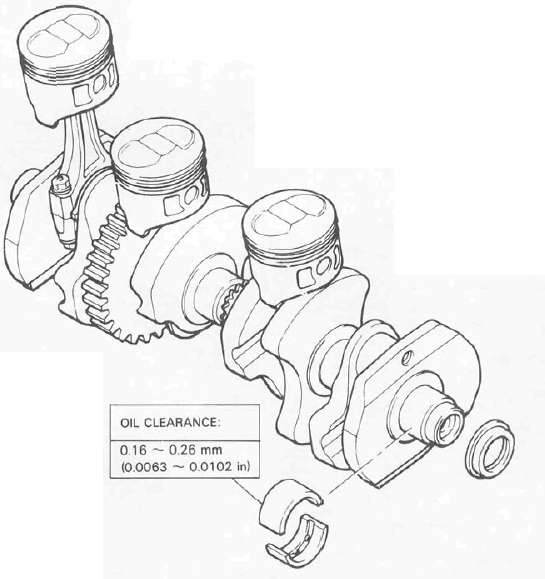
CRANKSHAFT/PISTON
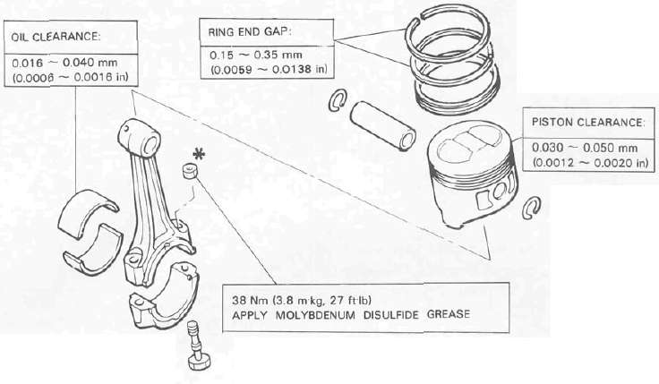
. WHEN INSTALLING THE CONNECTING ROD. BE SURE THAT THE SECURING NUTS ARE ON TOP.
Engine assembly
- Read more about Upper Crankcase Assembly
- Log in to post comments
CRANKSHAFT/PISTON
. WHEN INSTALLING THE CONNECTING ROD. BE SURE THAT THE SECURING NUTS ARE ON TOP.
Engine assembly
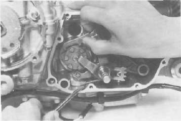
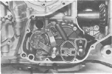
Oil pump removal and disassembly
1. Remove the strainer cover. Note the wire harness clip position.
2. Remove the oil pump secruing bolts and remove the sprocket cover and oil pump assembly.
Carburetor synchronization
The seat must be removed and the rear of the tank elevated to gain access to the vacuum connections and synchronizing screw.
NOTE:
The valve clearances must be set properly before synchronizing the carburetors.
7, Shifter assembly a. Install the shift shaft assembly with the stopper lever.
b. Install the shift lever assembly with the positioning spring is properly located on the stopper pin and the teeth should be set properly as shown.
The following special tools are not available but can be constructed for the final gear disassembly and assembly:
PRESS TOOL NO. 1

PRESS TOOL NO. 2

GEAR CASE HOLDING TOOL
To ensure maximum performance, long service, and safe operation, note the following: Tire air pressure
Always check and adjust the tire pressures before operating the motorcycle.
Circuit diagram 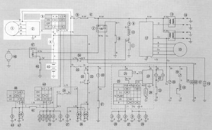
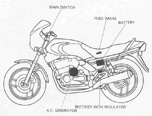
A. C. Generator
1. Checking method
a. Connect D. C. voltmeter to the battery terminals.
b. Start the engine.
FRONT MASTER CYLINDER
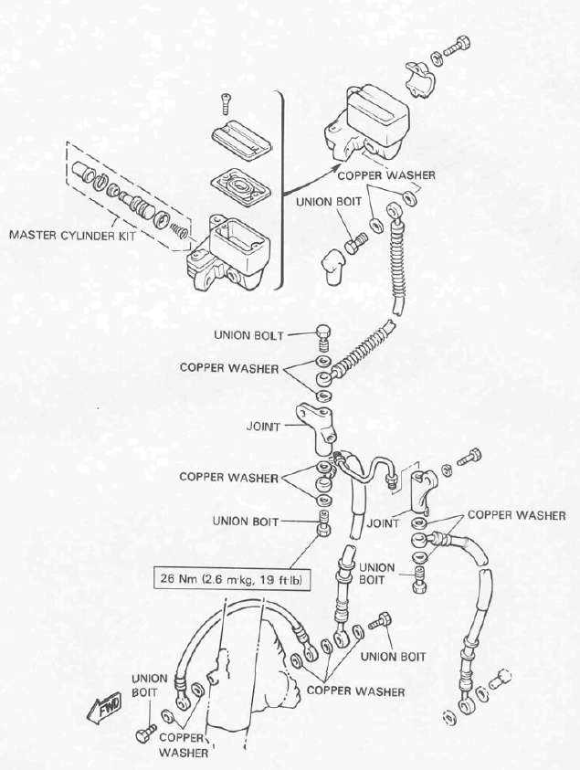
REAR MASTER CYLINDER

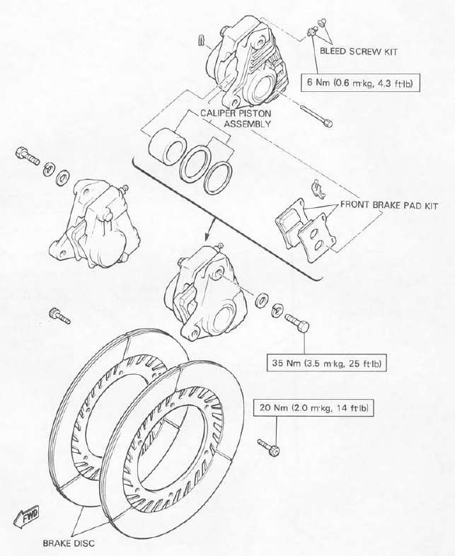
FRONT BRAKE CALIPER
REAR BRAKE CALIPER
|
1 |
Steering System Lock-to-iock Angle |
|
Taper roller bearing KOYO 32005 |