Chapter 5, FUEL SYSTEM
Chapter 5, FUEL SYSTEMFUEL SYSTEM
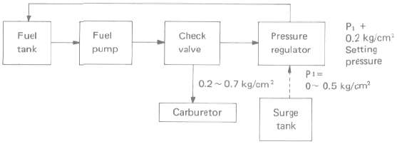
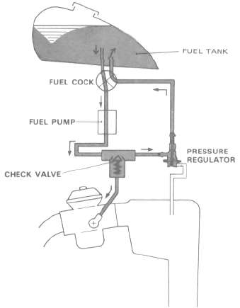
The fuel system is made up of a fuel tank, fuel cock, an electrical fuel pump, a check valve, a pressure regulator, and the carburetors.
Fuel is fed to the carburetor float chambers by the boost pressure picked up from the surge tank. The excess pressure (which determines the rate of flow of the fuel) is channeled through the pressure regulator back into the fuel tank. The pressurized fuel goes through the check valve to the carburetor float chambers. Unlike conventional carburetors, the fuel in the float chamber must be pressurized so that it can be metered into the venturiis. If it were not pressurized, the higher pressure with which the air enters the carburetors as the result of turbocharging would prevent any fuel from leaving the carburetors.
Components and Layout
Components and LayoutFUEL SYSTEM COMPONENTS
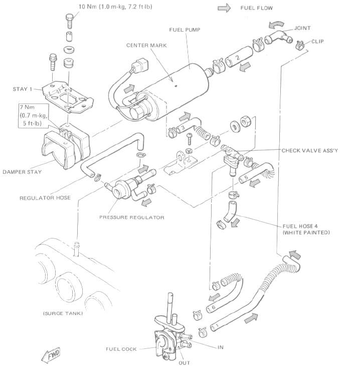
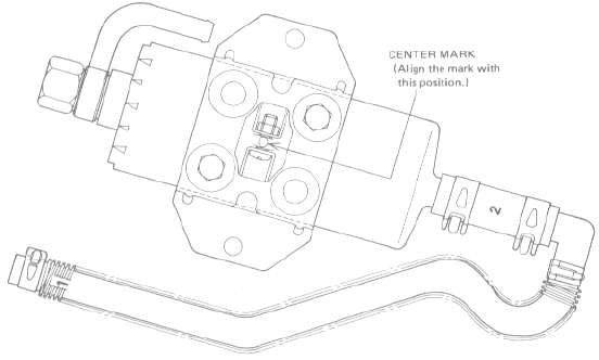
NOTE:
1. Connect fuel hose 1 to the fuel cock "OUT".
2. Connect fuel hose 6 to the fuel cock "IN".
3. The center mark on the fuel pump should be located in the upper center of the damper stay as shown in the illustration.
HOW TO LAYOUT FUEL HOSES
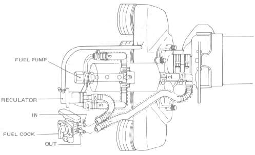
FUEL PUMP LOCATION
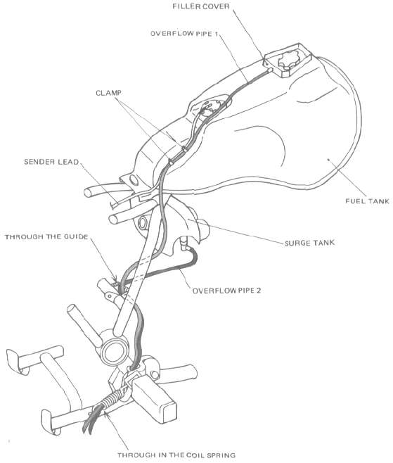
OVERFLOW PIPE ROUTING
Fuel Pump
Fuel PumpFUEL PUMP
The fuel pump is operated by a DC motor that is directly coupled to the pump. Fuel from the fuel cock is drawn into the pump, flows around the motor to the outlet at the opposite end of the housing, and then is fed through the check valve.
The fuel pump is connected to the electric starter circuit and begins pumping fuel when the starter is made to operate. The pump is protected by the circuits that sense AC generator output should the engine stall and a ballast switch, which shuts the fuel pump off should the motorcycle fall over.

The pump is made up of a housing, a rotor, and a series of rollers. While the rotor is turning, the rollers, which are pushed against the housing by centrifugal force, trap fuel. The fuel thus trapped is squeezed out as the rotor further turns. In the event of restricted fuel flow in the system, a spring loaded relief valve is used to work at 2.5 kg/cm2. This valve relieves excess pressure that could build up in the fuel system.

FUEL PUMP CIRCUIT
This fuel pump can run when the starter motor is running or when the engine is running.

FUEL PUMP OPERATION
1. Main Switch On:
The ignition system circuit is closed, but the fuel pump will not run.
2. Electric Starter Button On:
The electric starter begins to operate. Relay 2, in parallel with the electric starter, closes, thereby making the fuel pump operate,
3. Engine On.
When the engine is turned over, the AC generator creates voltage which keeps relay 2 on and the pump running.
4. Engine Stalls:
If the engine stalls, the AC generator does not produce voltage. Relay 2 is turned off, stopping the fuel pump. No other switches need be turned off.
5. Motorcycle Falls:
Should the motorcycle go down, the ballast switch turns on and relay 1 is turned off. This opens the ignition circuit which kills the engine. At the same time, the pump is also cutoff from its power supply and stops running.
Fuel pump specifications:
Consumption amperage: 2A or less
Output pressure: 98.1 kPa (1.0 kg/cm3, 14.2 psi)
CHECK VALVE
This valve replaces the traditional vacuum fuel cock. It is fitted to the system to prevent fuel flow to the carburetors when the engine is not running. If a pressure of 19.6 kPa (0.2 kg/cm3, 2.8 psi) is created on the intake side of the valve, fuel flow will be 3.5L/hour to the carburetors.

SECTION A-A:

PRESSURE REGULATOR
This regulator is closed when the engine is at a stop and open when the engine is running, thereby controlling the feed pressure (i.e., fuel flow) in the range of the charging pressure plus an additional 0.2 kg/cm2. Spring-and-diaphragm control of pressure is used to ensure the proper manifold-/fuel pressure difference. The spring end of the regulator is thus open to the engine manifold. As the pressure exceeds 0.2 kg/cm1, the diaphragm opens the regulator, causing excess fuel to return into the fuel tank.


Carburettor and Intake
Carburettor and IntakeCARBURETOR
The carburetor is a fully-enclosed type BS30; float chamber ventilation is opened to the surge tank, because the float chamber must always be under boost pressure in order to supply sufficient fuel to the venturi.

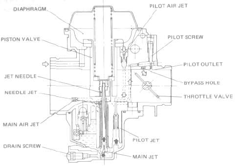
CARBURETOR SECTION VIEW
 AIR
AIR
 MIXTURE
 FUEL
FUEL
STARTER SYSTEM

 AIR
AIR
 MIXTURE
 FUEL
FUEL
PRESSURE-SEALED CARBURETORS
These carburetors have been specifically developed for use with a turbocharger. Because they are subjected to high intake pressures created by the turbocharger, they too must be pressurized to work effectively. To achieve this, the throttle valve shaft and starter plunger have 0 rings to prevent pressure leaks, and to ensure that they do not leak, special passages deliver pressurized air to complete the seal. Air will leak from the throttle shaft and starter plunger O-rings, but this is normal. Should, however, fuel begin to leak from these passages, the carburetor must be serviced immediately.


THROTTLE VALVE SHAFT (A)

STARTER PLUNGER IBI
AIR CLEANER AND CRANKCASE VENTILATION SYSTEM

 FRESH AIR
 BLOW-BY GAS