Chapter 6, ELECTRICAL
Chapter 6, ELECTRICALWiring Diagram
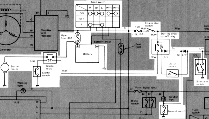
Wiring DiagramXJ750RH WIRING DIAGRAM

Electric Starting System
Electric Starting System
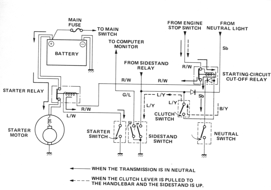
Starting circuit operation
The starting circuit on this model consists of the starter motor, starter relay, and the starting-circuit cut-off relay. If the engine stop switch and the main switch are both on, the starter motor can operate only if:
a. The transmission is in neutral (the neutral switch is on).
or if
b. The clutch lever is pulled to the handlebar (the clutch switch is on) and the sidestand is up (the sidestand switch is on.)
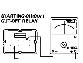
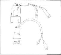
Starting-circuit cut-off relay inspection
1. Open the seat, and remove the fuel tank.
2. Remove the starting-circuit cut-off relay from the frame, and disconnect the connector.
The starting-circuit cut-off relay prevents the starter from operating when neither of these conditions has been met. In this instance, the starting-circuit cut-off relay is off so current cannot reach the starter motor.
When one or both of the above conditions have been met, however, the starting-circuit cut-off relay is on, and the engine can be started by pressing the starter switch.
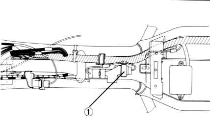
1. Starting-circuit cut-off relay
3. Check the resistance of the relay coil windings with the pocket tester. If the resistance is not within specification, replace the relay.
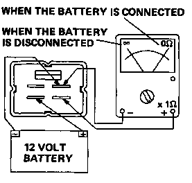
4. Check the relay function with a 12 volt battery and the pocket tester. Connect the leads as shown in the illustration. If the resistance readings do not equal those shown in the illustration, replace the relay.
5. Check the diode in the starting circuit cut-off relay with the pocket tester as shown in the illustration. Replace the relay if the diode is damaged.
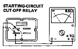
NOTE:
Only the Yamaha Pocket Tester will give a 9.5Ω reading when testing continuity. The particular characteristics of other testesr will very the continuity test readings.
Charging System
Charging SystemD. CHARGING SYSTEM

B. A.C. Generator
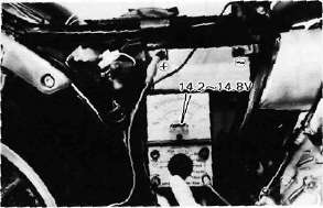
1. Checking method.
a. Connect D.C. voltmeter to the battery terminals.
b. Start engine.
c. Accelerate engine to approximately 2,000 r/min or more and check generated voltage.
Generated voltage: 14.5± 0.3V
d. If the indicated voltage cannot be reached, then perform the tests in step 2.
— CAUTION:---
Never disconnect wires from the battery while the generator is in operation. If the battery is disconnected, the voltage across the generator terminals will increase, damaging the semiconductors.
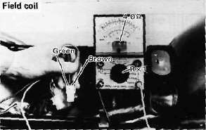
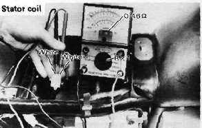
2. Resistance test of field coil and stator coil.
Check the resistance between terminals. If resistance is out of specification, coil is broken. Check the coil connections. If the coil connections are good, then the coil is broken inside and it should be replaced.
|
Field coil resistance: |
(Green-Brown) |
|
4.0Ω ± 10% at 20°C (68°F) |
|
|
Stator coil resistance |
(White-White) |
|
0.46Ω ± 10% at 20°C (68°F) |
|
C. Voltage Regulator
The IC Voltage Regulator is a small and, normally, very reliable component. Due to its construction, it is lightweight and free from the wear and misadjustment associated with mechanical voltage regulators. If the following inspection reveals that the regulator is faulty, it cannot be adjusted and must be replaced.
1. Checking IC Voltage Regulator
a. Remove the seat.
b. Remove the left side cover.
c. Measure the specific gravity of the battery fluid. If it is less than 1.260, remove the battery and recharge until it is more than 1.260. (See page 124 for charging procedures)
d. Check the battery terminals and couplers for looseness.
e. Connect two Yamaha pocket testers to the regulator coupler as illustrated.
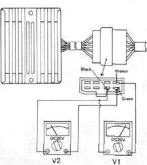
—CAUTION:
Be careful not to let the tester leads short circuit when connecting them to the regulator snap connector leads.
f. Turn the main switch on. Make sure that V2 is less than 1.8V.
NOTE:
Do not turn on lights or signals.
g. Make sure that V2 gradually increases up to 9 ~ 11V when the engine is started and its revolutions go up.
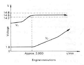
h. Make sure that Vi maintains the level of 14.2 ~ 14.8V even when engine revolutions increase.
i. If these levels are not maintained, the regulator is defective and must be replaced.
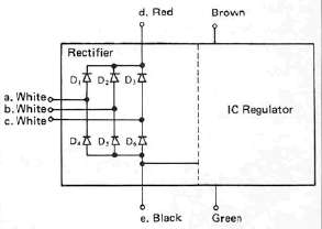
2. Checking the silicon rectifier a. Check the silicon rectifier as specified using the Yamaha pocket tester.
|
Checking element |
Pocket tester connecting point |
Good |
Replace (element shorted) |
Replace (element opened) |
|
|
(+) (red) |
(-) (black) |
||||
|
Di |
d |
a |
0 |
0 |
X |
|
a |
d |
X |
0 |
X |
|
|
D2 |
d |
b |
O |
0 |
X |
|
b |
d |
X |
0 |
X |
|
|
D3 |
d |
c |
0 |
0 |
X |
|
c |
d |
X |
0 |
X |
|
|
D4 |
a |
e |
0 |
0 |
X |
|
e |
a |
X |
0 |
X |
|
|
D5 |
b |
e |
0 |
0 |
X |
|
e |
b |
X |
o |
X |
|
|
D6 |
c |
e |
o |
0 |
X |
|
e |
c |
X |
0 |
X |
|
0 : Continuity
x : Discontinuity (∞)
b. Even if only one of the elements is broken, replace the entire assembly.
— CAUTION:---
The silicon rectifier can be damaged if subjected to overcharging. Special care should be taken to avoid a short circuit and/or incorrect connection of the positive and negative leads at the battery. Never connect the rectifier directly to the battery to make a continuity check.
Ignition System
Ignition SystemE. IGNITION SYSTEM
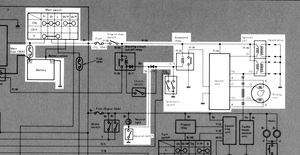
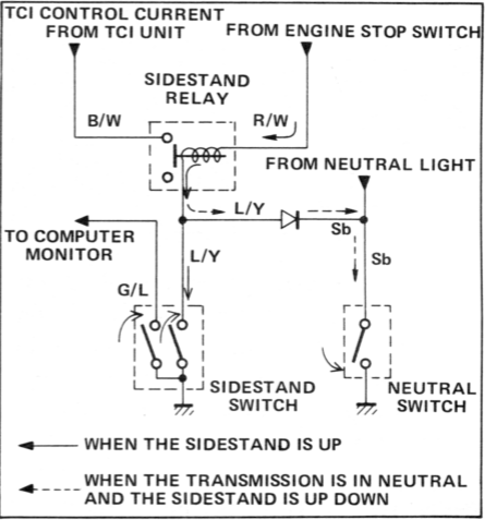
Above circuit diagram shows only ignition circuit in wiring diagram.
Description
This model is equipped with a battery operated, fully transistorized, breakerless ignition system. By using magnetic pickup coils, the need for contact breaker points is eliminated. This adds to the dependability of the system by eliminating frequent cleaning and adjustment of points and ignition timing. The TCI (Transistor Control Ignition) unit incorporates an automatic advance circuit controlled by signals generated by the pickup coil. This adds to the dependability of the system by eliminating the mechanical advancer. This TCI system consists of two units; a pickup unit and an ignitor unit.
NOTE:
The ignition circuit can be operated only when the sidestand is up (the sidestand switch is on) or the transmission is in neutral.
Operation
The TCI functions to the same principle as a conventional DC ignition system with the exception of using magnetic pickup coils and a transistor control box (TCI) in place of contact breaker points.
1. Pick-up unit

1. Pick-up coils
The pickup unit consists of two pickup coils and a flywheel mounted onto the crankshaft. When the projection on the flywheel passes a pickup coil, a signal is generated and transmitted to the ignitor unit. The width of the projection on the flywheel determines the ignition advance.
2- Ignitor unit

This unit controls when form, duty control, switching, electronic ignition advance, etc. They duty control circuit reduces electrical consumption by controlling the duration of the primary ignition current.
The ignitor unit also has a protective circuit for the ignition coil. If the ignition switch is on and the crankshaft is not turning, the protective circuit interrupts the current flow to the primary coil after a few seconds. When the crankshaft is turning, however, the ignitor unit sends current to the primary coil.
CAUTION:
Do not run the engine without any spark plug cap(s) in place. Due to the high secondary voltage, it is possible to damage the internal insulation of the secondary coil.
3. Sidestand relay
The sidestand relay operates by shorting the TCI control current. When the side-stand is down, the sidestand relay is closed, and the TCI control current is grounded through the sidestand relay. Thus, the engine will not run with the sidestand down unless the transmission is in neutral.
D. Troubleshooting/Inspection
1. The entire ignition system can be checked for misfire and weak spark using the Electro Tester. If the ignition system will fire across a sufficient gap, the entire ignition system can be considered good. If not, proceed with individual component tests until the problem is found.
a. Warm up engine thoroughly so that all electrical components are at operating temperature.
b. Stop the engine and connect the tester as shown.

c. Start the engine and increase the spark gap until misfire occurs. (Test at various r/min between idle and red line.)
Minimum spark gap: 6 mm (0.24 in)
CAUTION:
Do not run engine in neutral above 6,000 r/min for more than 1 or 2 seconds.
2. If the ignition system should become inoperative, the following troubleshooting aids will be useful.
| Check entire ignition for connections |
---------------> Poor connection |
Correct |
▼ OK ▼ |
Check battery for voltage and specific gravity |
---------------> Low voltage & specific gravity |
Recharge battery |
▼ OK ▼ |
Check fuse and fuse connections | ---------------> Weak connection or open circuit |
Correct connection or replace fuse |
▼ OK ▼ |
Check resistance of ignition coil {primary and secondary) Primary: 2.5 Ω ± 10% at 20°C (68°F) Secondary: 11KΩ ± 20% at 20°C(68 F) |
---------------> If other than specified |
Replace ignition coil |
▼ OK ▼ |
Check pick-up coils for resistance Pick-up coil: 700 Ω ± 20% at 20°C (68°F) |
---------------> If other than specified |
Replace pick-up coil assembly |
▼ OK ▼ |
TCI unit is faulty, replace unit |
3. Ignition coil
a. Coil spark gap test.
1) Remove the fuel tank and disconnect the ignition coil from wire harness and spark plugs.
2) Connect the Electro Tester as shown.

3) Connect fully charged battery to tester.
4) Turn on spark gap switch and the increase gap to maximum unless misfire occurs first.
Minimum spark gap: 6 mm (0.24 in)
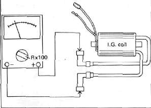
b. Direct current resistance test. Use a pocket tester or equivalent ohmmeter to determine resistance and continuity of primary and secondary coil windings.
Standard value: Primary coil resistance:
2.5Ω ± 10% at 20°C (68°F)
Secondary coil resistance:
11 KΩ ± 20% at 20% (68°F)
Primary coil check

Secondary coil check
4. Spark plug
The life of a spark plug and its discoloring vary according to the habits of the rider. At each periodic inspection, replace burned or fouled plugs with new ones of the specified type. It is actually economical to install new plugs often since it will tend to keep the engine in good condition and prevent excessive fuel consumption.
a. Inspection
1) Inspect and clean the spark plug every 4,000 km (2,500 mi) and replace after initial 13,000 km (8,000 mi).
2) Clean the electrodes of carbon and adjust the electrode gap to the specification.
b. Installation
Be sure to use the proper reach, type and electrode gap plug(s) as a replacement to
avoid overheating, fouling or piston damage.
Type:
BP7ES (NGK) or W22EP (ND) Electrode gap:
0.7 - 0.8 mm (0.028 - 0.031 in) Tightening torque:
2.0 m-kg (14.5 ft-lb)
Sidestand relay inspection
1. Open the seat, and remove the fuel tank.
2. Remove the sidestand relay from the frame, and disconnect the connector.

1. Sidestand relay
3. Check the resistance of the relay coil windings with the pocket tester. If the resistance is not within specification, replace the relay.

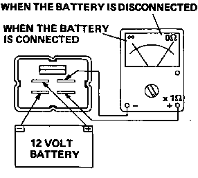
4. Check the relay contact breaker points with the pocket tester and a 12 bolt battery. Connect the leads as shown in the illustration. If the resistance readings do not equal those shown in the illustration, replace the relay.
Lighting System
Lighting SystemLIGHTING SYSTEM

Above circuit diagram shows only lighting circuit in wiring diagram.

B. Lighting Tests and Checks
The battery provides power for operation of the headlight, taillight, and meter lights. If none of the above operates, always check battery voltage before proceeding further. Low battery voltage indicates either a faulty battery, low battery water, or a defective charging system. See page 113 "CHARGING SYSTEM" for checks of battery and charging system. Also check fuse condition. Replace any "open" fuses. There are individual fuses for various circuits (see complete Circuit Diagram).
NOTE:
Check the headlight bulb first before performing the following check.
1. Headlight check NOTE:
When the engine is started, the headlight and meter lights come on automatically and the lights stay on until the main switch is turned to "OFF" even if the engine stalls.
|
HEADLIGHT DOES NOT COME ON WHEN ENGINE IS RUNNING |
Check for voltage on "W" wire to safety relay |
-----------> |
Check AC generator, diode, or wiring circuit |
▼ ▼ |
Check for battery voltage (12V) on "R/Y" wire to headlight relay |
-----------> No voltage |
Check fuse "Head or wiring circuit |
▼ Voltage OK ▼ |
Check for battery voltage (12V) on "L/B" wire from headlight relay |
-----------> No voltage |
Replace headlight relay |
|
HIGH BEAM AND/OR LOW BEAM DO NOT LIGHT |
Check for battery voltage at dimmer switch terminal |
-----------> |
Dimmer switch defective |
▼ Voltage OK ▼ |
Check for battery voltage at headlight high beam or low beam terminal |
-----------> |
Open or poor connection between headlight and dimmer switch terminal |
▼ Voltage OK ▼ |
Poor ground or poor connection of headlight wiring |
2. Taillight does not work:
a. Check bulb
b. Check for 12V on blue wire.
c. Check for ground on black wire to tail/brake light and/or license light assembly.
Signals
Signals
G. SIGNAL SYSTEM

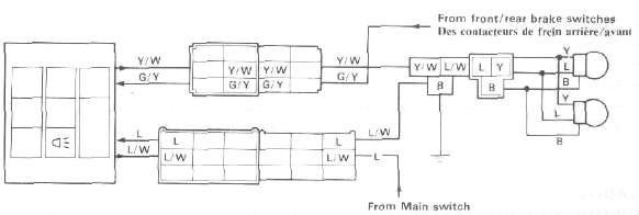
Above circuit diagram shows only signal circuit in wiring diagram.

B. Signal System Tests and Checks
The battery provides power for operation of the horn, brake light, indicator lights and flasher light. If none of the above operates, always check battery voltage before proceeding further. Low battery voltage indicates either a faulty battery, low battery water, or a defective charging system. See page 113 "CHARGING SYSTEM" for checks of battery and charging system. Also check fuse condition. Replace any "open" fuses. There are individual fuses for various circuits (see complete Circuit Diagram).
1. Horn does not work:
a. Check for 12V on brown wire to horn.
b. Check for good grounding of horn (pink wire) when horn button is pressed.
2. Brake light does not work:
a. Check bulb.
b. Check for 12V on yellow wire to brake light.
c. Check for 12V on brown wire to each brake light switch (front brake and rear brake switches).
3. Flasher light(s) do not work:
a. Check bulb.
b. Right circuit:
1) Check for 12V on dark green wire to light.
2) Check for ground on black wire to light assembly.
c. Left circuit:
1) Check for 12V on dark brown wire to light.
2) Check for ground on black wire to light assembly.
d. Right and left circuits do not work:
1) Check for 12V on brown/white wire to flasher switch on left handlebar.
2) Check for 12V on brown wire to flasher relay.
3) Replace flasher relay.
4) Replace flasher switch.
e. Check flasher self-canceling system. (Refer to flasher self-canceling system.)
4. Neutral light does not work:
a. Check bulb.
b. Check for 12V on sky blue wire to neutral switch.
c. Replace neutral switch.
6. Oil level warning light does not work:
a. Connect oil level switch (black/red wire) to ground. If light comes on, check for proper oil level.
b. If oil level is correct, replace oil level switch.
C. Self-Canceling Flasher System
1. Description:
The self-canceling flasher system turns off the turn signal after a period of time or distance involved in turning or changing lanes. Generally, the signal will cancel after either 10 seconds, or 150 meters (490 feet), whichever is greater. At very low speed, the function is determined by distance; at high speed, especially when changing speeds the canceling determination is a combination of both times and distance.
2. Operation:
The handlebar switch has three positions: L (left), OFF, and R (right). The switch lever will return to the "OFF" position after being pushed to L or R, but the signal will function. By pushing the lever in, the signal may be cancelled manually.
3. Inspection
If the flasher self-canceling system should become inoperative, proceed as follows:
a. Pull of the 6-pin connector from the flasher canceling unit, and operate the handlebar switch, if the signal operates normally in L, R, and OFF, the following are in good condition.
1) Flasher unit
2) Bulb
3) Lighting circuit
4) Handlebar switch light circuit
If (1) through (4) are in good condition, the following may be faulty:
1) Flasher canceling unit.
2) Handlebar switch reset circuit.
3) Speedometer sensor circuit.
b. Pull off the 6-pin connector from the flasher canceling unit, and connect a tester (ohms x 100 range) across the white/green and the black lead wires on the wire harness side. Turn the speedometer shaft. If the tester needle swing back and forth between 0 and ∞, the speedometer sensor circuit is in good condition. If not, the sensor to wire harness may be inoperative.
c. Pull the 6-pin connector from the flasher canceling unit. Check if there is continuity between the yellow/red lead wire on the wire harness side and the chassis.
Flasher switch OFF: ∞
Flasher switch L or R: 0 ohms
If the tester needle does not swing as indicated above, check the handlebar switch circuit and wire harness.
d. If no defect is found with the above three check-ups and the flasher canceling system is still inoperative, replace the flasher canceling unit.
e. If the signal flashes only when the handlebar switch lever is turned to L or R and it turns off immediately when the handlebar switch lever returns to center, replace the flasher canceling unit.
D. Switches
Switches may be checked for continuity with a pocket tester on the "ohm x 1" position. 1. Main switch
|
Switch Position |
Wire Color |
||
|
R |
Br |
L/Y |
|
|
ON |
0---- |
--0-- |
----0 |
|
OFF |
|
|
|
|
LOCK |
|
|
|
|
P (parking) |
0---- |
------ | ----0 |
2. "ENGINE STOP" Switch
|
Switch |
Wire Color |
|
|
Position |
R/W |
R/W |
|
RUN |
0---- |
----0 |
|
OFF |
|
|
3. "START" switch
|
Button Position |
Wire Color |
|
|
L/W |
Ground |
|
|
PUSH |
O----- |
----O |
|
OFF |
|
|
4. "LIGHTS" (Dimmer) switch
|
Switch Position |
Wire Color |
|||||
|
Y |
L/Y |
G |
G |
L/G |
Y/B |
|
|
HI |
0--- | --O |
|
0--- |
--O |
|
|
LO |
|
0--- |
--O |
|
O---- |
--O |
5. "TURN" switch
|
Switch Position |
Wire Color |
||||
|
Ch |
Br/W |
Dg |
Y/n |
Ground |
|
|
L |
0--- |
--O |
|
0--- |
--O |
|
L > N |
0--- |
--O |
|
|
|
|
N > Push |
|
|
|
|
|
|
R > N |
|
O--- |
--O |
|
|
|
R |
|
O--- |
--O |
0--- |
--O |
6. "HORN" Switch
|
Button Position |
Wire Color |
|
|
P |
Ground |
|
|
PUSH |
O--- |
------O |
|
OFF |
|
|
E. Battery
1. Checking
If the battery shows the following defects, it should be replaced.
a. The battery voltage will not rise to a specific value or no gassing occurs in any cell even after many hours of charging.
b. Sulfation of one or more cells is indicated by the plates turning white or an accumulation of material in the bottom of the cell.
c. Specific gravity readings after a long slow charge indicate a cell to be lower than any others.
d. Warpage or buckling of plates or insulators is evident.
WARNING:
Battery fluid is poisonous and dangerous, causing severe burns, etc. Contains sulfuric acid. Avoid contact with skin, eyes or clothing.
Antidote:
EXTERNAL-FLUSH with water.
INTERNAL-Drink large quantities of water or milk. Follow with milk of magnesia, beaten egg or vegetable oil. Call physician immediately.
Eyes: Flush with water for 15 minutes and get prompt medical attention.
Batteries produce explosive gases. Keep sparks, flame, cigarettes, etc., away. Ventilate when charging or using in enclosed space. Always shield eyes when working near batteries.
KEEP OUT OF REACH OF CHILDREN.
2. The service life of a battery is usually 2 to 3 years, but lack of care as described below will shorten the life of the battery.
a. Negligence in keeping battery topped off with distilled water.
b. Battery being left discharged.
c. Over-charging with heavy charge.
d. Freezing.
e. Filling with water or sulfuric acid containing impurities.
f. Improper charging voltage or current on new battery.
3. If the motorcycle is not to be used for a long time, remove the battery and have it stored. The following instructions should be observed:
a. Recharge the battery periodically.
b. Store the battery in a cool, dry place.
c. Recharge the battery before reinstallation.
|
Battery |
12N12A-4A-1 |
|
Electrolyte |
Specific gravity: 1.280 |
|
Initial charging current |
1.2 amp for 10 hours (new battery) |
|
Recharging current |
10 hours (or until specific gravity reaches 1.280) |
|
Refill fluid |
Distilled water (to maximum level line) |
|
Refill period |
Check once per month (or more often, required) |
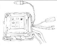
Computerized Monitoring System
Computerized Monitoring SystemComputerized Monitor System - Operation
Computerized Monitor System - Operation


Operation
NOTE: Before starting out on the road, check the motorcycle conditions using computerized monitor system.
1.
When the main switch is turned on, all seven liquid crystal displays
(LCDs) come on, with the fuel display indicating the amount of fuel in
the tank.
![]()
2.
When the engine is started, the system begins its scan of the
motorcycle conditions. From top to bottom all the LCDs flash on and
then off in sequence. If any one condition is found improper or
inadequate, the red warning light will begin flashing and the LCD for
the area in question will remain displayed.
3.
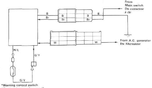
Warning light operation can be controlled by the warning control
switch. If the control switch is pushed once, the warning light glow
will change from a flashing to a steady one. If pushed again, the glow
will go out completely. Still another push on the switch brings back
the warning light operation all over again.
NOTE:
1. This switch operates only when a malfunction is displayed on an LCD.
2. Even if the warning light is made to glow; steady or to go out, it will begin flashing on with another malfunction.
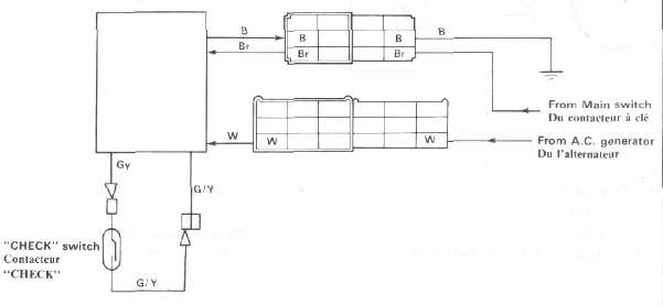
4.
The entire monitoring system condition can be checked by pushing the
check switch. The system will scan through the seven areas in sequence,
just as when the engine was first started, to assure the rider that the
system is functioning properly.

1. Turn indicator light
2. Neutral indicator light
3. High beam indicator light
4. Warning light
5. Display panel
6. Warning control switch
7. Check switch
(XJ 750R panel shown)
| CMS Operation Flow Chart | All circuits OFF | ▼ | Main switch ON | ▼ | Red warning light and all LCD readouts stay ON for self check. | ▼ | Engine Starts |
|
▼ | ► | The system automatically cycles once. (CMS monitors all functions during machine operation.) |
► | Red warning light FLASHES and a particular LCD readout stays ON | ◄ | ▲ | ▼ | ▼ | ▲ | ▲ | If all LCD readouts are OFF | ◄ |
Displayed function must be corrected immediately. |
▲ | ▲ | ▼ | ▼ | ▲ | ▲ |
Monitored functions are in good condition. |
Push Warning control switch | ▲ | ▲ | ▼ | ▼ | ▲ | ▲ | Press Check switch |
Red warning light stops flashing and stays on. LCD readout continues to stay ON. |
▲ | ▲ | ◄ | ▼ | ▲ | Push Warning control switch | ▲ | ▼ | ▲ | Main switch OFF |
Red warning light goes OFF |
▲ | ▼ | ▼ | ▲ | Operation stops. | Push Warning control switch | ▲ |
Display Panel
Sidestand
![]()
This indicator is displayed when the sidestand is extended. Be sure to retract it before starting out on the road.
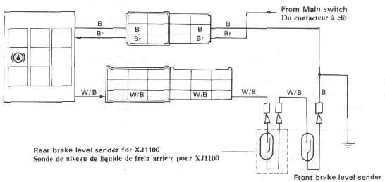
Brake fluid level
![]()
This indicator is displayed when the brake fluid level is below specification in the front brake master cylinder.
Do not run the motorcycle with a low brake fluid level for a long time or at high speeds.
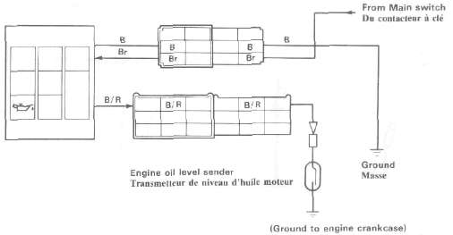
Engine oil level
![]()
This
indicator is displayed when the engine oil level is low. If it remains
displayed or keeps flickering while riding, add engine oil.
Do not run the motorcycle with a low engine oil level for a long time or at high speeds.
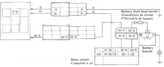
Battery fluid level
![]()
This indicator is displayed when the battery fluid level is low. If it remains displayed, add distilled water.
CAUTION:
Continuous riding with a low battery fluid level will damage the battery.
Headlight bulb
![]()
This
indicator is displayed when the headlight bulb is burned out. If it
remains displayed, have it replaced and correctly adjusted.
Tail/brake light bulbs
![]()
This
indicator is displayed when the taillight and/or brake light bulbs are
burned out. If it remains displayed, have it replaced.
Fuel amount
![]()
This indicator is displayed when the fuel level is low. If it remains displayed or keeps flickering while riding, add fuel.
This indicator is displayed the amount of fuel in the tank. If the four blocks are displayed, the fuel is full.
IMPORTANT NOTICE Headlight, Tail/brake lights
* Bulbs of wattage other than specified mustn't be used.
Extra electric accessories mustn't be connected to the each light circuit.
Reason:
1. CMS calculates the amount of current flow in these circuits.
2. Excessive current flow in these circuits may damage the control units, or
3. LCD panel may not display failure. Battery Sender
* Clean battery sender terminal occasionally. (Approximetry every 5,000 km)
Reason: The terminal, though made of lead, can be corroded on its surface, resulting in malfunction.
Other Senders
* Do not modify or add any electrical load to any sender.
Reason: Any modification may result in CMS malfunction.
Handling
* The instrument panel mustn't be subjected to any water splashes or steam from underneath.
* The display panel mustn't be pressed hard or given any shock.
* A magnet or other magnetized objects mustn't be put near the display panel.
CMS Components
CMS ComponentsSender locations
HTML clipboard
XJ750

System Components
|
Sidestand switch |
Brake fluid level sender |
Engine oil level sender |
|
|
|
|
|
Battery fluid level sender |
Headlight bulb |
|
|
Tail/Brake light bulb |
||
|
|
|
|
|
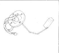
Fuel level sender |
Computerized monitor |
LCD panel |
|
|
|
|
|
Computer unit |
"Check" switch |
"Warning" switch |
|
|
|
|


Symbol Identification
|
|
Conductor |
|
Bulb (single filament) |
|
|
|
Crossing conductor (not joined) |
|
Bulb (Double filament) |
|
|
|
Conductors joined |
|
Wire connector |
|
|
|
Ground (earth) |
|
Diode |
|
|
|
Resistor (adjustable) |
|
Sender |
|
|
|
Switch |
|
|
Power input |
|
|
Switch
|
|
|
Power output |
|
|
Fuse |
|
Battery |
|


Color Code
|
Br |
Brown |
Gy |
Gray |
|
B |
Black |
G/R |
Green/ Red |
|
L |
Blue |
G/L |
Green/ Blue |
|
W |
White |
G/Y |
Green/Yellow |
|
Y |
Yellow |
L/W |
Blue/ White |
|
G |
Green |
Y/W |
Yellow/ White |
|
Y/G |
Yellow/ Green |
B/R |
Black/ Red |
|
W/R |
White/Red |
G/W |
Green/ White |
|
W/B |
White/ Black |
W/L |
White/Blue |
|
R/B |
Red/Black |
Y/B |
Yellow/Black |
NOTES ON TROUBLESHOOTING
Before checking the computerized monitor, check the following points:
Battery: Be sure to use a fully-charged battery for troubleshooting.
Motorcycle: The motorcycle to be inspected must be of standard specification (not modified after shipped from the factory).
1. No optional parts for users are fitted to the motorcycle. (Decoration light, etc.)
2. No modification is made to any part of the motorcycle. (Change in electrical circuits, etc.)
3. The level displayed on each monitor is correct, (the fuel, engine oil, brake fluid, and battery fluid levels are correct.)
4. All light bulbs are in good condition.
Tester: Use a Yamaha Pocket tester for checking of electrical parts.
CMS Monitor Troubleshooting
CMS Monitor TroubleshootingProblem: THE COMPUTERIZED MONITOR DOES NOT COME ON WITH THE MAIN SWITCH TURNED ON.
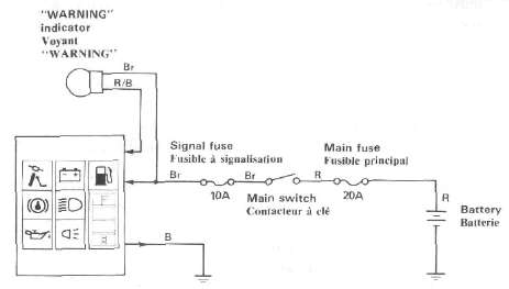
| Operate the horn and flashers to check the charged state of the battery. | Bad ► |
• Recharge the battery. • Check the fuse and main switch. |
| Good | ||
Apply 12 volts to the brown lead on the monitor side through the 6-P coupler in the headlight body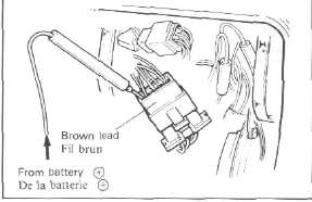 |
Comes on ► |
• Grounding is poor. (Check the black lead.) |
| Does not come on ▼ | ||
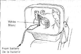
Ground the black lead of the coupler to the engine while applying 12 volts. |
||
|
Does not come on▼ |
||
|
• LCD is faulty. |
Problem: THE MONITOR COMES ON, BUT THE "WARNING" INDICATOR DOES NOT.
|
|
|
|
|
Check the WARNING indicator bulb. |
Burnt out |
• Replace. |
|
Good ▼ |
|
|
|
• CMS is faulty. |
|
|

Problem: WHEN THE ENGINE HAS STARTED, THE MONITOR DOES NOT AUTO-SCAN.

|
*Main switch is ON. Disconnect the W lead of the 9-P coupler (on the monitor side) in the headlight body. Apply DC 12V to the W lead.
|
Does not scan ► |
• CMS is faulty. |
| Scans ▼ | ||
|
• AC generator is faulty. |
Problem: THE MONITOR DOES NOT SCAN WITH THE CHECK SWITCH PUSHED.
| With the main switch turned on, all monitors come on, and when the engine has started, auto-scan starts. | Does not operate ► |
• See the "Troubleshooting" in the previous page. |
| Operates ▼ | ||
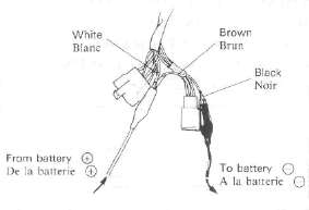
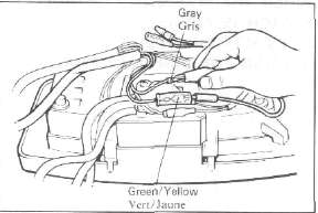
| Disconnect the connector adjacent to the check switch on the back of meter assembly.
Apply 12 volts to both the Brown and White leads, and ground the Black lead. Next, bring the Grey lead to directly contact the Green/ Yellow lead once, and separate them. |
Operates ► |
• Check switch is faulty. |
| Does not operate ▼ | ||
| • CMS is faulty. |
Problem: WHEN THE WARNING CONTROL SWITCH IS PUSHED, THE DISPLAY DOES NOT CHANGE. (DURING THE DISPLAY OF TROUBLE)
| Disconnect the connector adjacent to the "warning control" switch on the back of the meter assembly
Bring W/L to contact with G/Y, then disconnect it. By repeating this operation, check to see that the light switches from one to another while flashing.
|
Switches ► |
• Warning control switch is faulty. |
| Does not change ▼ | ||
| • CMS is faulty. |

CMS Sensors Troubleshooting
CMS Sensors TroubleshootingSIDESTAND MONITOR

|
*Main switch is ON. Disconnect the 3-P coupler on the side-stand side.
|
Operates as specified in a. and b. ► |
• Side-stand switch is faulty.
|
| Measure voltage between G/L and B on harness side. | ||
| Less than 12V ▼ | ||
Disconnect the G/L lead from the 9-P coupler (on the monitor side) in the headlight body, and ground it.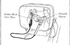 |
Operates ► |
• Green/blue lead is broken. |
| Does not operate ▼ | ||
|
• CMS is faulty. |
NOTE: If the side stand monitor comes on with the main switch turned on, CMS is faulty.
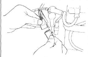
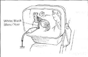
BRAKE FLUID MONITOR
|
*Main switch is ON. Disconnect the connector of white/black lead |
|
|
|
Ground the W/B female connector with a jumper wire |
Operates |
• Brake level sender is faulty.
|
|
Does not operate ▼ |
|
|
|
Disconnect the W/B lead of the 9-P coupler (on the monitor side) in the headlight body, and ground it. |
Operates |
• White/Black lead is broken. |
| Does not operate ▼ | ||
|
• CMS is faulty. |


NOTE: If the "BRK" monitor comes on with the main switch turned on, CMS is faulty.
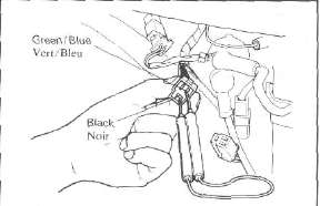
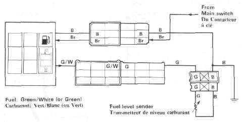
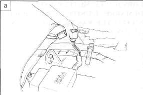
ENGINE OIL MONITOR
|
*Main switch is ON. Disconnect the connector adjacent to the oil level sensor located under the crankcase.
|
Operates as specified in a. and b. ► |
• Engine oil level sender is faulty.
Note: When installing the engine oil level sender, be sure to use a hand wrench to tighten the bolt. If it is tightened by using a compressed air driven tool, sender malfunctions may occur. |
| Does not operate ▼ | ||
Disconnect the B/ R lead of the 9-P coupler (on the monitor side) in the headlight body, and ground it. |
Operates ► |
• Black/red lead is broken. |
| Does not operate ▼ | ||
|
• CMS is faulty. |


NOTE: If the oil level monitor comes on with the main switch turned on, CMS is faulty.
BATTERY MONITOR
|
*Main switch is ON. Disconnect the connector adjacent to the battery sensor.
a. When disconnected: "BATT" monitor comes on.
b. When 12V is applied to the wire harness side of W/R lead: "BATT" monitor goes off. |
Operates as specified in a. and b. ► |
• Battery fluid level sender is faulty.
NOTE: Polish the battery sender terminals with sandpaper, check the sender again. |
| Does not operate ▼ | ||
|
Disconnect the 2-P connector of the main switch in the headlight body.
a. When disconnected: "BATT" monitor comes on.
|
Operate as specified in a. and b. ► |
• Main switch is faulty.
|
| Does not operate ▼ | ||
|
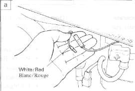
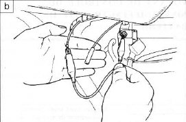
Disconnect the W/R lead of the 9-P coupler (on the monitor side) in the headlight body.
b. When 12V is applied to the monitor side of W/R lead: "BATT" monitor goes off.
|
Operates as specified in a. and b. ► |
• White/Red lead is broken. (Main switch to 9-P coupler) |
| Does not operate ▼ | ||
| • CMS is faulty. |

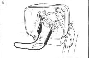
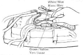
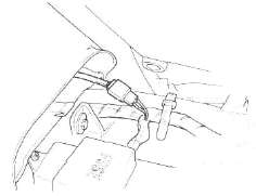
FUEL MONITOR
'Fuel tank is full.
| *Main switch is ON. *Engine running Disconnect the 3-P coupler on the fuel tank side. a. When disconnected: Fuel monitor comes on but the display of the remaining amount of fuel goes off.
b. When green/white lead is grounded: The remaining amount (4 blocks) of fuel is displayed, but the fuel monitor goes off.
|
Operates as specified in a. and b. ► |
• Fuel level sender is faulty.
|
| Does not operate ▼ | ||
|
Disconnect the G/W lead at the 9-P coupler (on the monitor side) in the headlight body, and ground it.
|
Operates ► |
• Green/White lead is broken. |
| Does not operate ▼ | ||
|
• CMS is faulty. |


NOTE: If both monitor and blocks are displayed with the main switch turned on, CMS is faulty.
Troubleshooting Headlight, Brakelight, Taillight issues and other CMS Troubles
Troubleshooting Headlight, Brakelight, Taillight issues and other CMS TroublesProblem: HEADLIGHT DOES NOT COME ON. (MONITOR DOES NOT LIGHT.)

Light lead connections:
HI: Yellow to Yellow/Green (or Yellow/Red)
Lo: Green to Green/Red
NOTE: On the XJ750, no lights will come on before the engine starts.
|
Disconnect the 3-P coupler (for headlight) in the headlight body, and check voltage. |
12V ► |
Headlight bulb is burnt out. |
| Less than 12V ▼ | ||
| Measure input voltage on the wire harness side through the 6-P coupler in the headlight body. Hi: Yellow to Ground Lo: Green to Ground  • • |
Reads 12V ► |
• CMS is faulty |
| Less than 12V ▼ | ||
|
• Dimmer switch Check the condition of these parts according to the electrical section of the service manual. |

Problem: HEADLIGHT COMES ON AND MONITOR WILL NOT GO OFF.
• CMS is faulty.
• LCD is faulty.
• Connector is faulty.
NOTE: If the monitor (HEAD) comes on with the main switch turned on, both LCD and connector are in good condition. Replace CMS.
Problem: THE HEADLIGHT BULB IS NOT BURNT OUT, BUT THE MONITOR COMES ON.
• Yellow/Green lead is broken.
• Green/Red lead is broken.
• Black lead is broken.
• Connector is loose.
TAIL/BRAKE LIGHT DOES NOT COME ON. (MONITOR DOES NOT COME ON.)
Light lead connections:
Tail: Blue-Blue/White
Brake: Green/Yellow- Yellow/White (or Yellow/Black)
|
Disconnect the 3-P coupler of the taillight, and measure voltage. |
12V ► |
• Burnt taillight bulb
|
|
Less than 12V ▼ |
||
|
Disconnect the Y/W and L/W leads from the monitor side of the 6-P and 9-P couplers, and check voltage. |
12V |
• Broken Yellow/White lead
|
|
Less than 12V ▼ |
|
|
| Measure voltage of the L lead and G/Y lead on the wire harness side. Tail: Blue lead from Main switch Brake: Green/Yellow lead from brake switches   |
12V ► |
• CMS is faulty. |
| Less than 12V ▼ | ||
|
• Brake: Check the brake switch and leads. |
|
|


EXAMPLES OF OTHER TROUBLES
The computerized monitor system may malfunction under the following conditions, though it is in good condition. The term "malfunction" means an erratic change in the display when the computerized monitor is not operated.
1. The battery is in a state of extremely low voltage. The computerized monitor system is so designed that it operates normally when a specific voltage is input. Therefore, if the battery has almost run down or sulfation, the system may malfunction.
2. The computerized monitor system is interfered by radio noise. The system has a protective device against radio noise, but some special radio noise may cause the system to malfunction.
Radio noise can be produced in the following cases:
a. When spark plugs without resistor are used on an engine for which spark plugs with built-in resistor should be used.
b. When a special horn is used.
EXAMPLES OF ERRATIC LC. DISPLAYS
If any one of the following symptoms appears, the L.C. display is considered to be faulty.
1. Part of the L.C. display is chipped off.

2. The deflecting plate has scratches or cavities.

3. Glass is cracked or chipped,
4. Contrast is uneven on the same display.
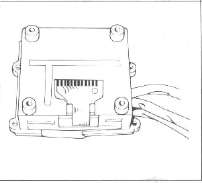
Cleaning and Replacing the CMS Display/ Microcomputer
Cleaning and Replacing the CMS Display/ MicrocomputerCleaning and replacement
Use the following procedure to replace the LCD unit or the microcomputer unit.

1. Remove the headlight lens and the two headlight-body holding bolts. This will give you easy access to the instrument-panel holding nuts.
2. Disconnect the wire connectors in the headlight assembly that lead to the instrument panel.
3. Disconnect the speedometer cable.
4. Disconnect the instrument-panel holding nuts, and remove the panel.
5. Remove the three nuts which secure the instrument-panel mounting bracket, and remove the bracket.
6. Place the instrument panel assembly on a clean work surface, and remove the back panel.
7. Remove the four Phillips-head screws which secure the LCD/microcomputer, and remove the unit.
8. Remove the four screws which hold the LCD display holder.
9. Very carefully turn the display holder over, and completely remove the five display plate holding screws. Remove the LCD reflector and the display plate.
10. Detach the wire connector from its indexing points.
Disconnect the wire connector carefully. Do not pull on the wire connector. It is indexed and could be damaged if you pull on it. Do not touch the connector contacts. They are gold plated.
11. Remove the display plate and the LCD unit.
12. Clean the display plate and the LCD unit.
CAUTION:
a. Use compressed-air lens cleaner (as used on cameras) to clean the display and the LCD unit. Do not use shop air for this purpose.
b. Use a soft cloth. Do not use cotton. It will leave lint deposits which will interfere with the delicate contacts.
c. Very carefully clean the LCD unit because it is possible to generate enough static electricity to damage it.
13. Reinstall the LCD unit into the display holder.
Do not touch the LCD connector with bare hands.
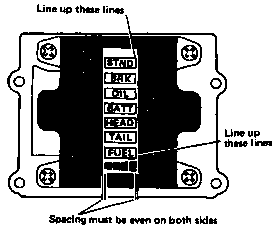
IMPORTANT NOTE:
The LCD unit must line up as shown in the illustration to seal the LCD unit properly.
14. Reinstall the LCD reflector so that the shiny surface faces toward the LCD unit.
15. Carefully place the wire connector on the LCD connector and seat it on its two indexing points. Install the display plate and carefully screw in the wire connector indexing screw first. Then screw in the remaining four holding screws. Do not overtighten the screws.
|
Tightening torque: |
|
|
3 mm: |
10cm-kg(0.7ft-lb) |
|
|
(Use LOCTITE) |
|
4 mm: |
24cm-kg(1.7ft-lb) |
16. Reinstall the display holder on the microcomputer.
IMPORTANT NOTE:
Before reinstalling the components, connect the LCD assembly to the motorcycle and check that it is function properly.
17. Reinstall the entire unit in the instrument panel.
18. Reinstall the instrument panel back to the motorcycle.
19. Check that the COM system is functioning properly.
CMS Wiring Diagram
CMS Wiring DiagramXJ750
