Engine
EngineContents of Engine Maintenance:
Valve Adjustments
Valve AdjustmentsVALVE CLEARANCE ADJUSTMENT
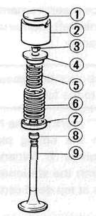
(1)Pad (2) Valve lifter (3) Valve retainer (4)Spring seat (5)inner spring (6) Outer spring (7) Spring seat (8) Oil seal (9) Valve
|
A |
VALVE CLEARANCE (COLD): |
|
|
B |
Intake: |
0.11 -0.15 mm (0.0043-0.0059 in) |
|
C |
Exhaust: |
0.16-0.20 mm (0.0063-0.0079 in) |
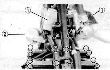
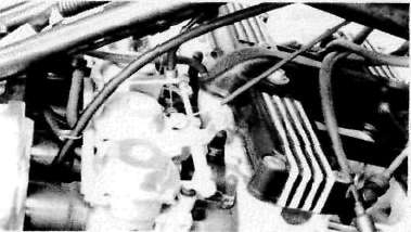
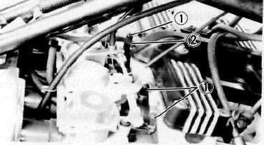
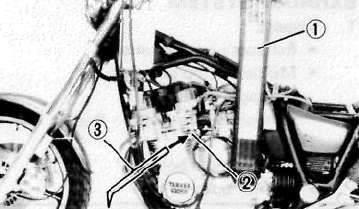
Removal
1. Remove:
• Seat
• Fuel tank
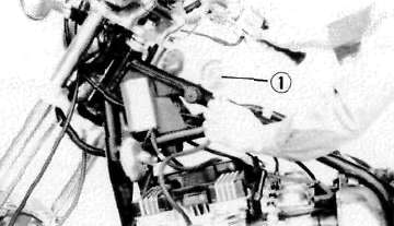
• Ignition coil covers (1)
• Horns with stay (2)
2. Disconnect:
• Spark plug caps
3. Remove:
• Spark plugs
• Cylinder head cover
4. Remove:
• Emblem plate (Left)
Inspection and Adjustment
1. Measure:
• Valve clearance
NOTE:
Be sure piston is at Top Dead Center (TDC) on compression stroke when measuring clearance.
Valve clearance measurement steps:
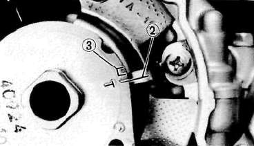
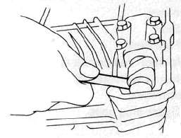
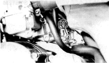
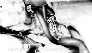
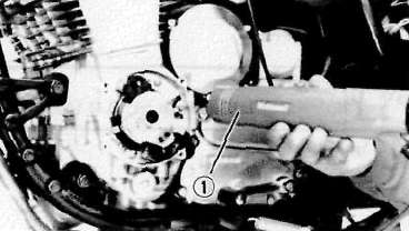
• Turn the crankshaft counterclockwise with a 19 mm spanner (1) .
NOTE:
Valve clearance must be measured when the engine is cool to the touch.
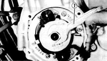
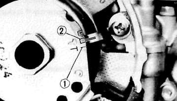
• Align the "T" mark (for the No. 1 or No. 4 cylinder) on the timing plate with the stationary pointer (2). When the "T" mark is aligned with the stationary pointer (2), the piston is at top dead center TDC.
(3) Firing range for No. 1 cylinder
• Measure the valve clearance using a Feeler Gauge.
• Record the measured amount if the clearance is incorrect.
Intake Valve (cold): 0.11 —0.15 mm (0.0043 ~ 0.0059 in)
Exhaust Valve (cold): 0.16 —0.20 mm (0.0063 ~ 0.0079 in)
• Measure valve clearance, in sequence, for Nos. 2, 4, and No. 3 cylinders. Out of specification — Adjust clearance.
Firing Sequence: 1-2-4-3
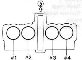
(5) Front
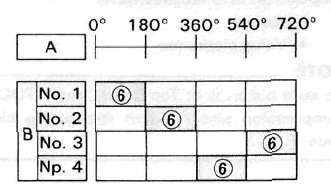
A Crankshaft counterclockwise turning angle.
B Cylinder
(6) Combustion
2. Adjust:
• Valve clearance
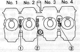
Valve clearance adjustment steps:
• Position the valve lifter slots (intake and exhaust) opposite each other.
• Turn the camshaft until the lobe fully depresses the valve lifter and opens the valve.
• Attach the Tappet Adjusting Tool (1) (YM-01245) onto the cylinder head.
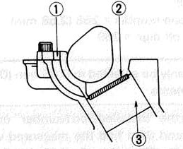
NOTE:
Make sure that the tool contacts the lifter (3) only, and not the pad (2).
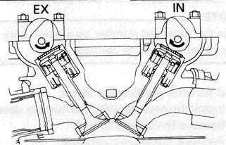
• Carefully rotate the camshaft so that the pads can be removed. To avoid cam touching the adjusting tool, turn cams as shown.
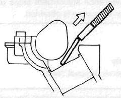
Intake: Carefully rotate CLOCKWISE. Exhaust: Carefully rotate COUNTERCLOCKWISE.
• Remove the pads (2) from the lifters. Use a small screwdriver and a magnetic rod for removal.Note pad numbers.
• Select the proper valve adjusting pad from the chart below:
|
Pad range |
Pad Availability: 25 increments |
|
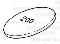
No. 200 - 2.00mm (0.079 in) |
Pad stepped in 0.05 mm (0.002 in) increments |
NOTE:
Thickness of each pad is marked on the pad face that contacts the valve lifter (not the cam).
• Round off the hundredths digit of the original pad number to the nearest 0.05 mm increment.
|
Hundredths digit |
Rounded valve |
|
0 or 2 |
0 |
|
5 |
NOT ROUNDED OFF |
|
8 |
10 |
EXAMPLE:
Original pad number = 258 (2.58 mm)
Rounded off digit = 260
NOTE:
Pad can only be selected in 0.05 mm (0.002 in) increments.
Determine the required replacement pad thickness by one of the two following methods:
Shim calculation method:
Since all shims come in .05mm (.002") increments, you can quickly calculate the required size without a chart.
If the measured clearance is within 0.05mm (0.002") of the required clearance, then no change is needed.
If the measured clearance greater than 0.05mm (0.002") but 0.10mm (0.004") or less different than the required clearance then the next size shim is required.
If the measured clearance greater than 0.10mm (0.004") but 0.15mm (0.006") or less different than the required clearance then the next size shim is required.
Clearances that are too small require thinner shims. Clearances that are too large require thicker shims.
Example: Required exhaust valve clearance is 0.16~0.20mm. Measured clearance is 0.12mm (gap too small). Installed shim is Y270. Required shim is one size thinner: Y265.
Shim Chart Lookup Method:
• Locate the "Installed Pad Number" on the chart, and then find the measured valve clearance. The point where these coordinates intersect is the new pad number.
NOTE:
Use the new pad number as a guide only as the number must be verified.
Pad number verification steps:
• Install the new pad with the number down.
• Remove the adjusting tool.
• Recheck the valve clearance.
• If the clearance is incorrect, repeat all of the clearance adjustment steps until the proper clearance is obtained.
Assembly
1. Reverse removal steps.
NOTE:
Inspect the head cover gasket and replace it if damaged.
2. Tighten:
• Cylinder head cover bolts
• Fuel tank bolts
Head Cover Bolt:
10Nm(1.0mkg, 7.2 ftlb)
Fuel Tank Bolt:
10Nm(1.0rrvkg, 7.2 ftlb)
INTAKE
|
MEASURED |
INSTALLED PAD NUMBER |
||||||||||||||||||||||||
|
200 |
205 |
210 |
215 |
220 |
225 |
230 |
235 |
240 |
245 |
250 |
255 |
260 |
265 |
270 |
275 |
280 |
285 |
290 |
295 |
300 |
305 |
310 |
315 |
320 |
|
|
0.00 - 0 05 |
200 |
205 |
210 |
215 |
220 |
225 |
230 |
235 |
240 |
245 |
250 |
255 |
260 |
265 |
270 |
275 |
280 |
285 |
290 |
295 |
300 |
305 |
310 |
||
|
0.06 - 0 10 |
200 |
205 |
210 |
215 |
220 |
225 |
230 |
235 |
240 |
240 |
260 |
255 |
260 |
265 |
270 |
275 |
280 |
285 |
290 |
295 |
300 |
305 |
310 |
315 |
|
|
0 11 - 0.15 |
|||||||||||||||||||||||||
|
0 16 - 0.20 |
205 |
210 |
215 |
220 |
225 |
230 |
235 |
240 |
245 |
250 |
255 |
260 |
265 |
270 |
275 |
280 |
285 |
290 |
295 |
300 |
305 |
310 |
315 |
320 |
|
|
0.21 - 0.25 |
210 |
215 |
220 |
225 |
230 |
235 |
240 |
245 |
250 |
255 |
200 |
265 |
270 |
275 |
280 |
285 |
290 |
295 |
300 |
305 |
310 |
315 |
320 |
||
|
0 26 - 0.30 |
215 |
220 |
225 |
230 |
235 |
240 |
245 |
250 |
255 |
260 |
265 |
270 |
275 |
280 |
285 |
290 |
295 |
300 |
305 |
310 |
315 |
320 |
|||
|
0.31 - 0.35 |
220 |
22ft |
230 |
23ft |
240 |
245 |
250 |
255 |
260 |
265 |
270 |
275 |
280 |
285 |
290 |
295 |
300 |
305 |
310 |
315 |
320 |
||||
|
0 36 - 0 40 |
225 |
230 |
235 |
240 |
245 |
250 |
255 |
260 |
265 |
270 |
275 |
280 |
285 |
290 |
295 |
300 |
305 |
310 |
315 |
320 |
|||||
|
0 41 - 0 45 |
230 |
235 |
240 |
245 |
250 |
255 |
260 |
265 |
270 |
275 |
280 |
285 |
290 |
295 |
300 |
305 |
310 |
315 |
320 |
||||||
|
0.46 - 0 50 |
235 |
240 |
245 |
250 |
255 |
260 |
265 |
270 |
275 |
280 |
285 |
290 |
295 |
300 |
305 |
310 |
315 |
320 |
|||||||
|
0 51 - 0.55 |
240 |
245 |
250 |
255 |
260 |
265 |
270 |
275 |
280 |
285 |
290 |
295 |
300 |
305 |
310 |
315 |
320 |
||||||||
|
0 56 - 0 60 |
245 |
250 |
255 |
260 |
265 |
270 |
275 |
280 |
285 |
290 |
295 |
300 |
305 |
310 |
315 |
320 |
|||||||||
|
0.61 - 0.65 |
250 |
255 |
260 |
265 |
270 |
275 |
280 |
285 |
290 |
295 |
300 |
305 |
310 |
315 |
320 |
||||||||||
|
0 66 - 0.70 |
255 |
260 |
265 |
270 |
275 |
280 |
285 |
290 |
295 |
300 |
305 |
310 |
315 |
320 |
|||||||||||
|
0.71 - 0.75 |
260 |
265 |
270 |
275 |
280 |
285 |
290 |
295 |
300 |
305 |
310 |
315 |
320 |
||||||||||||
|
0.76 - 0 80 |
265 |
270 |
275 |
280 |
285 |
290 |
295 |
300 |
305 |
310 |
315 |
320 |
|
||||||||||||
|
0.81 - 0.85 |
270 |
275 |
280 |
285 |
290 |
295 |
300 |
305 |
310 |
315 |
320 |
||||||||||||||
|
0 86 - 0 90 |
275 |
280 |
285 |
290 |
295 |
300 |
305 |
310 |
315 |
320 |
VALVE CLEARANCE (cold): |
||||||||||||||
|
0.91 - 0.95 |
280 |
285 |
290 |
295 |
300 |
305 |
310 |
315 |
320 |
||||||||||||||||
|
0.96 - 1 00 |
285 |
290 |
295 |
300 |
305 |
310 |
315 |
320 |
0.11 to 0.15 mm (0.004 — 0.006 in) |
||||||||||||||||
|
1.01 - 1.05 |
290 |
295 |
300 |
305 |
310 |
315 |
320 |
||||||||||||||||||
|
1.06 - 1.10 |
295 |
300 |
305 |
310 |
315 |
320 |
Measured clearance is 0.32 mm (0.013 in) |
||||||||||||||||||
|
1.11 - 1.15 |
300 |
305 |
310 |
315 |
320 |
||||||||||||||||||||
|
1.16 - 1.20 |
305 |
310 |
315 |
320 |
Pad number : (example) |
||||||||||||||||||||
|
1 21 - 1 25 |
310 |
315 |
320 |
||||||||||||||||||||||
|
1 26 - 1 30 |
315 |
320 |
Pad No. 255 = 2.55 mm (0.100 in) |
||||||||||||||||||||||
|
1.31 - 1 35 |
320 |
||||||||||||||||||||||||
EXHAUST
|
MEASURED |
INSTALLED PAD NUMBER |
||||||||||||||||||||||||
|
200 |
205 |
210 |
215 |
220 |
225 |
230 |
235 |
240 |
245 |
250 |
255 |
260 |
265 |
270 |
275 |
280 |
285 |
290 |
295 |
300 |
305 |
310 |
315 |
320 |
|
| 0.00 - 0 05 |
200 |
205 |
210 |
215 |
220 |
225 |
230 |
235 |
240 |
245 |
250 |
255 |
260 |
265 |
270 |
275 |
280 |
285 |
290 |
295 |
300 |
305 |
|||
|
0.06 - 0 10 |
200 |
205 |
210 |
216 |
220 |
225 |
230 |
235 |
240 |
245 |
250 |
255 |
260 |
265 |
270 |
275 |
280 |
285 |
290 |
295 |
300 |
305 |
310 |
||
|
0 11 - 0.15 |
200 |
205 |
210 |
215 |
220 |
225 |
230 |
235 |
240 |
245 |
250 |
255 |
260 |
265 |
270 |
275 |
280 |
285 |
290 |
295 |
300 |
305 |
310 |
315 |
|
|
0 16 - 0.20 |
|||||||||||||||||||||||||
|
0.21 - 0.25 |
205 |
210 |
215 |
220 |
225 |
230 |
235 |
240 |
246 |
250 |
255 |
260 |
265 |
270 |
275 |
280 |
285 |
290 |
295 |
300 |
305 |
310 |
315 |
320 |
|
|
0 26 - 0.30 |
210 |
215 |
220 |
225 |
230 |
235 |
240 |
245 |
250 |
255 |
260 |
265 |
270 |
275 |
280 |
285 |
290 |
295 |
300 |
305 |
310 |
315 |
320 |
||
|
0.31 - 0.35 |
216 |
220 |
225 |
230 |
235 |
240 |
24ft |
260 |
255 |
2ft0 |
20ft |
270 |
275 |
280 |
285 |
290 |
295 |
300 |
305 |
310 |
315 |
320 |
|||
|
0 36 - 0 40 |
220 |
225 |
230 |
235 |
240 |
245 |
250 |
255 |
260 |
265 |
270 |
275 |
280 |
285 |
290 |
295 |
300 |
305 |
310 |
315 |
320 |
||||
|
0 41 - 0 45 |
225 |
230 |
235 |
240 |
245 |
250 |
255 |
260 |
265 |
^70 |
2'5 |
280 |
285 |
290 |
295 |
300 |
305 |
310 |
315 |
320 |
|||||
|
0.46 - 0 50 |
230 |
235 |
240 |
245 |
250 |
255 |
260 |
265 |
270 |
275 |
280 |
285 |
290 |
295 |
300 |
305 |
310 |
315 |
320 |
|
|||||
|
0 51 - 0.55 |
235 |
240 |
245 |
250 |
255 |
260 |
265 |
270 |
275 |
280 |
285 |
290 |
295 |
300 |
305 |
310 |
315 |
320 |
|||||||
|
0 56 - 0 60 |
240 |
245 |
250 |
255 |
260 |
265 |
270 |
275 |
280 |
285 |
290 |
295 |
300 |
305 |
310 |
315 |
320 |
||||||||
|
0.61 - 0.65 |
245 |
250 |
265 |
260 |
265 |
270 |
275 |
280 |
285 |
290 |
295 |
300 |
305 |
310 |
315 |
320 |
|||||||||
|
0 66 - 0.70 |
250 |
255 |
260 |
265 |
270 |
275 |
280 |
285 |
290 |
295 |
300 |
305 |
310 |
315 |
320 |
||||||||||
|
0.71 - 0.75 |
255 |
260 |
265 |
270 |
275 |
280 |
285 |
290 |
295 |
300 |
305 |
310 |
315 |
320 |
|||||||||||
|
0.76 - 0 80 |
260 |
265 |
270 |
275 |
280 |
285 |
290 |
295 |
300 |
305 |
310 |
315 |
320 |
||||||||||||
|
0.81 - 0.85 |
265 |
2 70 |
275 |
280 |
285 |
290 |
295 |
300 |
306 |
310 |
315 |
320 |
|||||||||||||
|
0 86 - 0 90 |
270 |
275 |
280 |
285 |
290 |
295 |
300 |
305 |
310 |
316 |
320 |
VALVE CLEARANCE (cold): |
|||||||||||||
|
0.91 - 0.95 |
276 |
280 |
285 |
290 |
295 |
300 |
305 |
310 |
316 |
320 |
|||||||||||||||
|
0.96 - 1 00 |
280 |
285 |
290 |
295 |
300 |
305 |
310 |
315 |
320 |
0.16 - 0.20 mm (0.006 - 0.008 in) |
|||||||||||||||
|
1.01 - 1.05 |
285 |
290 |
295 |
300 |
305 |
310 |
315 |
320 |
|||||||||||||||||
|
1.06 - 1. 10 |
290 |
295 |
300 |
305 |
310 |
315 |
320 |
Measured clearance is 0.32 mm (0.013 in) |
|||||||||||||||||
|
1. 11 - 1. 15 |
295 |
300 |
305 |
310 |
315 |
320 |
|||||||||||||||||||
|
1. 16 - 1. 20 |
300 |
305 |
310 |
315 |
320 |
Pad number : (example) |
|||||||||||||||||||
|
1 21 - 1 25 |
305 |
310 |
315 |
320 |
|||||||||||||||||||||
|
1 26 - 1 30 |
310 |
315 |
320 |
Pad No. 255 = 2.55 mm (0.100 in) |
|||||||||||||||||||||
|
1.31 - 1 35 |
320 |
||||||||||||||||||||||||
Spark Plug, Emmissions, Exhaust and Carburetor
Spark Plug, Emmissions, Exhaust and Carburetor
SPARK PLUG
1. Remove:
• Spark plug(s)
2. Inspect:
• Electrode (1) Wear/Damage — Replace.
• Insulator color (2)
3. Measure:
• Plug gap (3)
Use a Wire Gauge or Feeler Gauge. Out of specification — Regap.
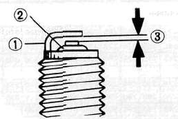
0.7 ~ 0.8 mm (0.028 - 0.31 in)
Clean the plug with a spark plug cleaner if necessary-
Standard Spark Plug: BP8 ES (NGK) W24EP-U (NIPPONDENSO)
Before installing a spark plug, clean the gasket surface and plug surface.
4. Tighten:
• Spark plug(s)
20 Nm (2.0 mkg, 14ftlb)
NOTE:
Finger-tighten the spark plug(s) before torquing to specification.
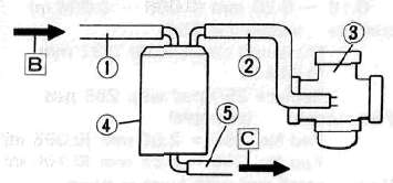
CANISTER (For California Only)
This model is equipped with a canister to prevent the discharging of fuel vapor into the atmosphere.
1. Inspect:
• Hoses (1) (2) (5) Cracks/Damage — Replace. Clog - Clean.
• Canister (4) Cracks/Damage — Replace.
3 Carburetor [B] From fuel tank [C] To atmosphere
A EMISSION HOSE ROUTING
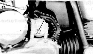
CRANKCASE VENTILATION SYSTEM
1. Inspect:
• Crankcase ventilation hose ® Cracks/Damage — Replace.
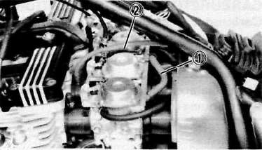
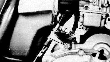
FUEL LINE
1. Inspect:
• Fuel hose (1)
• Vacuum hose (2) Cracks/Damage — Replace.
INTAKE MANIFOLD
1. Tighten:
• Carburetor clamps
• Carburetor joint bolts
2. Inspect:
• Carburetor joint
• Gaskets Cracks/Damage — Replace.
EXHAUST SYSTEM
1. Inspect:
• Exhaust pipe gasket(s) (1)
• Muffler clamp gasket(s) (2) Damage — Replace. Exhaust gas leakage — Repair.
2. Tighten:
• Exhaust pipe bolts
• Muffler bolts
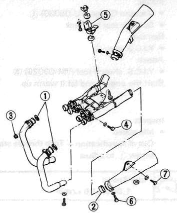
Exhaust Pipe Flange (3) :
10 Nm (1.0 m-kg, 7.2ft-lb)
Exhaust Pipe Clamp (4) :
20 Nm (2.0 m-kg, 14ftlb)
Muffler Bracket (5) :
25 Nm (2.5 m-kg, 18 ft-lb)
Exhaust Chamber Mount (7) :
20 Nm (2.0 m-kg, 14 ft-lb)
Muffler Clamp (6) :
20 Nm (2.0 m-kg, 1 4 ft-lb)
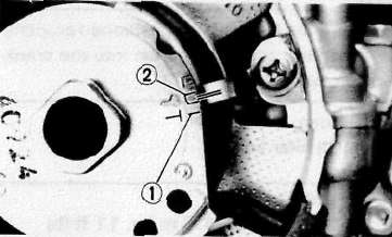
IDLE SPEED/CARBURETOR SYNCHRONIZATION
IDLE SPEED
1. Adjust
• Idle speed
Warm up the engine and turn the throttle stop screw (1) to adjust.
Idle Speed
1,050 + 50 r/min
Carburetor Adjustment.
Carburetors must be adjusted to open and close simultaneously.
NOTE:
Valve clearance must be set properly before synchronizing the carburetors.
1. Remove:
• Seat
• Fuel tank
2. Disconnect:
• Vacuum plugs (1)
• Vacuum hose (2)
3. Install:
• Vacuum Gauge (YU-08030) (1)
• Suitable test fuel tank
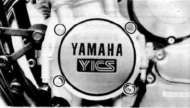
4. Remove:
• Y.I.C.S. plug (2)
5. Attach:
• Y.I.C.S. shutoff tool (YM-08025) (3)
6. Start the engine and let it warm up.
7. Inspect:
• Idle speed
Out of specification — Turn throttle stop screw (1) to adjust.
Idle Speed
1,050 ±50 r/min
8. Adjust:
• Carburetor synchronization
Carburetor synchronization adjustment steps:
• Synchronize the carburetor No. 1 to the carburetor No. 2 by turning the synchronizing screw (1) until the both gauge readings are the same.
• Rev. the engine for a fraction of a second, two or three times, and check the synchronization again.
Vacuum Pressure at Idle Speed:
23.99 kPa (180 mm Hg, 7.09 in Hg)
Vacuum Synchronous Difference:
0.67 kPa (5 mm Hg, 0.2 in Hg)
• Repeat the above steps to synchronize the carburetor No. 4 to the carburetor No. 3 by turning the synchronizing screw (3) until the both gauge readings are the same.
• Repeat the same steps to synchronize No. 3 carburetor to No. 1 carburetor, then turn synchronizing screw (2) until both gauge readings are the same.
Engine Oil
Engine Oil
At 5°C (40°F) or Higher:
SAE 20W40 Type SE Motor Oil
At 15°C (60°F) or Lower:
SAE 10W30 Type SE Motor Oil
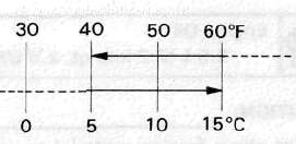
NOTE:
Recommended engine oil classification; API Service "SE", "SF" type or equivalent (e.g. "SF-SE", "SF-SE-CC", "SF-SE-SD" etc.)
Oil Level Measurement
1. Check
• Oil level
Oil level low — Add sufficient oil.
Oil level visual inspection steps:
• Place the motorcycle on its center stand and warm up the engine for several minutes.
NOTE:
Position the motorcycle straight up when checking oil level, a slight tilt to the side can produce false readings.
• Stop the engine and visually check the oil level through the level window (1).
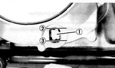
(2) Maximum (3) Minimum
Oil Change (Without filter)
1. Warm up the engine for several minutes, then place a receptacle under the engine.
2. Remove:
• Oil filler cap
3. Remove:
• Engine drain plug (1)
4. Tighten:
• Drain plug
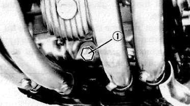
Engine Drain Plug:
43 Nm (4.3 m-kg, 31 ft-lb)
5. Fill:
• Crankcase
Engine Oil
2.5 L (2.2 imp qt, 2.6 US qt)
CAUTION:
Do not allow foreign material to enter the crankcase.
6. Install:
• Filler cap
Oil Change (With filter)
1. Warm up the engine and place a receptacle under the engine.
2. Remove:
• Oil filler cap
• Drain plug
Drain the engine oil.
3. Remove:
• Oil filter bolt (1)
• Filter cover (2)
4. Tighten:
• Drain plug
Engine Drain Plug:
43 Nm (4.3 m-kg, 31 ft-lb)
5. Install:
• Oil filter bolt (1)
• Spring (2)
• Washer (3)
• Oil filter (New) (4)
• O-ring (5)
• Oil filter assembly
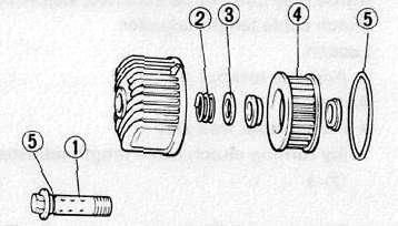
• Be sure the O-ring (5) is positioned properly.
• Fit the filter cover projection into the crank-case cover slot.
6. Tighten:
• Oil filter bolt
Oil Filter Bolt:
15 Nm (1.5 mkg, 11 ftlb)
7. Fill:
• Crankcase
Engine Oil:
2.8 L (2,5 imp qt, 3.0 US qt)
8. Install:
• Oil filler cap
9. Warm up the engine and check for oil leaks. Stop the engine instantly if leaking occurs.
Leaks — Check cause.
10. Check:
• Oil level
Level low — Add sufficient oil.
Clutch, Timing and Compression
Clutch, Timing and CompressionCLUTCH ADJUSTMENT
1. Loosen:
• Adjuster locknut (1)
2. Adjust:
• Clutch lever free play (3)
(by turning adjuster (2) in or out)
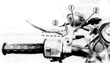
Free play:
2-3 mm (0.08 - 0.12 in)
If free play can not be adjusted, adjust by clutch cable length adjuster.
3. Loosen:
• Adjuster locknut (1)
4. Adjust:
• Clutch lever free play
(by turning clutch cable length adjuster (2) )
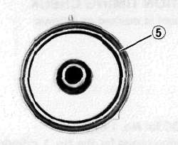
IGNITION TIMING CHECK
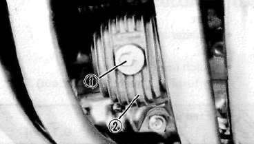
Flywheel is marked as follows:
(1) TDC for No. 1 cylinder
(2) Firing range for the No. 1 cylinder
1. Check:
• Ignition timing
Ignition timing check steps:
• Remove the cover.
• Connect the Timing Light (YM-33277) i to No. 1 cylinder spark plug lead.
• Warm up the engine and let it idle at the specified idle speed of 1,050 ± 50 r/min.
• Visually check the stationary pointer in the timing window to verify it is within the required firing range indicated on the flywheel.
Incorrect firing — Check timing plate and/or pickup assembly (tightness damage)
Refer to CHAPTER 6, "ELECTRICAL" for further information.
(1) TDC for No. 1 cylinder
(2) Firing range for the No. 1 cylinder
COMPRESSION PRESSURE MEASUREMENT
NOTE:
Insufficient compression pressure will result in performance loss.
1. Measure:
• Valve clearance
Out of specification — Adjust.
2. Warm up the engine.
3. Remove:
• Spark plugs
Compression pressure measurement steps:
• Install the Compression Gauge (YU-33223) (1) using an adapter.
• Crank over the engine with the electric starter (be sure the battery is fully charged) with the throttle wide-open until the compression reading on the gauge stabilizes.
• Check readings with specified levels (See chart).
Compression Pressure (at sea level):
Standard: 1,078 kPa (11 kg/cm2, 156 psi)
Minimum: 882 kPa (9 kg/cm2, 128 psi)
Maximum: 1,176 kPa (12 kg/cm2, 171 psi)
When cranking the engine, ground all of the spark plug leads to prevent sparking.
• Repeat the previous steps for the other cylinders.
• If pressure falls below the minimum level:
1. Squirt a few drops of oil into the affected cylinder.
2. Measure the compression again.
|
Compression Pressure (with oil introduced into cylinder) |
|
|
Higher than without oil |
Worn or damaged pistons |
|
Same as without oil |
Defective ring(s). valves, cylinder head gasket or piston is possible. |
|
Above maximum level |
Inspect cylinder head, valve surfaces, or piston crown for carbon deposits. |
NOTE:
The difference between the highest and lowest cylinder compression readings must not vary more than the specified value.
Difference Between Each Cylinder:
Less than 98 kPa (1 kg/cm2,14 psi)